SLAM
Chapter description
In this tutorial, we will walk you through the map creation process and discuss the SLAM algorithm, which consists of two parts: mapping and localization. The gmapping package will be used for mapping, the amcl package will be used to locate the robot on the map. Mapping is usually a necessary element to create more advanced autonomous driving systems. In addition, thanks to the knowledge of the map, we can complete the location of the robot. This is because we can compare the currently received sensor data and match it to the map. To do this, you will need to collect data from the RPLiDAR on board your ROSbot.
You can run this tutorial on:
Repository containing the final effect after doing all the ROS Tutorials you can find here
Introduction
SLAM (simultaneous localization and mapping) is a technique for creating a map of environment and determining robot position at the same time. It is widely used in robotics. While moving, current measurements and localization are changing, in order to create map it is necessary to merge measurements from previous positions.
For definition of SLAM problem we use given values (1,2) and expected values (3,4):
- Robot control
- Observations
- Robot trajectory
- Robot trajectory estimates are determined with:
- environment map
How SLAM work?
To perform an accurate and precise SLAM, one of the simplest solutions is to use a laser scanner and an odometry system (speed measurement system based on encoder data). However, due to the imperfections of the sensors, the map creation process is much more difficult. Why? Because various imperfections, e.g. caused by wheel slippage, can cause the same wall to be classified as two objects. To counteract unwanted changes, these algorithms use various tricks, such as the Monte Carlo method, which will be described in detail when discussing the amcl package. Note, however, that the gmapping algorithm also performs similar operations to improve the quality of the map. For more details check this video.
Laser scanner
In this example we will use RPLiDAR (laser scanner). For ROSbot, you can find a repository online containing rplidarNode from the rplidar_ros package to run RPLiDAR, but using a prepared docker is much simpler. The container will automatically configure and run rplidarNode. Upon startup, the node sends scans to topic /scan with a message of type sensor_msgs/LaserScan.
To test your sensor works type:
- ROSbot
- Gazebo simulator
docker compose up -d rosbot ros-master rplidar
After few seconds LiDAR should start spinning and new /scan topic should appear.
roslaunch rosbot_bringup rosbot_tutorial.launch world:=maze
For Gazebo you do not need any additional nodes, just start simulator and laser scans will be already published to appropriate /scan topic.
In case there are no scans showing, there may be a problem with laser scanner plugin for Gazebo.
Some GPUs, mainly the integrated ones have problems with proper rendering of laser scanner. To solve it, you will have to change the used plugin to CPU based. Go to file rosbot.gazebo located in rosbot_description/src/rosbot_description/urdf, comment out section succeeding <!-- RpLidar using GPU --> line with <!-- to begin comment and --> to end comment and uncomment section succeeding <!-- RpLidar using CPU --> line by deleting <!-- and -->.
You should have /scan topic in your system. You can examine it with rostopic list. It is possible to echo data but you will get lots of output, which is hard to read. Better method for checking the /scan topic is to use RViz. Run RViz and click Add. In new window select By topic tab and from the list select /scan. In visualized items list find position Fixed Frame and change it to base_link. To improve visibility of scanned shape, you may need to adjust one of visualized object options, set value of Style to Points. You should see many points which resemble shape of obstacles surrounding your robot. You can also add a RobotModel in RViz and and enable keyboard controls to watch how data change.
rosrun teleop_twist_keyboard teleop_twist_keyboard.py
SLAM with gmapping
To build the map we will use the slam_gmapping node from the gmapping package. This node subscribes to the /scan topic to obtain data about the surrounding environment. In addition, it subscribes to /tf messages to obtain the position of the laser scanner and the robot relative to the starting point. Thanks to the position and laser data, the algorithm can determine the distance of the robot from the surrounding obstacles and on this basis create an occupation map. This map is published in topic /map in message nav_msgs/OccupancyGrid.
To run this node it is necessary to set few parameters. There are many parameters provided by gmapping node. All the parameters are in the gmapping documentation, and the most important ones are described below:
base_frame- name of frame related with robot, in our case it will bebase_linkodom_frame- name of frame related with starting point, in our case it will beodommap_update_interval- Time between map updates, in our case it will be3.0secondsmaxUrange- The maximum usable range of the laser, in our case it will be15.0meters
All above parameters we set in new slam.launch file.
<launch>

  <arg name="use_gazebo" default="false" />

  <!-- Gazebo -->
  <group if="$(arg use_gazebo)">
      <param name="use_sim_time" value="true" />
      <include file="$(find rosbot_bringup)/launch/rosbot_tutorial.launch">
          <arg name="world" value="maze" />
      </include>
  </group>

  <!-- SLAM -->
  <node pkg="gmapping" type="slam_gmapping" name="gmapping">
      <param name="base_frame"            value="base_link"/>
      <param name="odom_frame"            value="odom" />
      <param name="map_update_interval"   value="3.0"/>
      <param name="maxUrange"             value="15.0"/>
  </node>

  <!-- Teleoperation - keyboard control -->
  <node pkg="teleop_twist_keyboard" type="teleop_twist_keyboard.py" name="teleop_twist_keyboard" output="screen"/>

</launch>
To run SLAM example type:
- ROSbot
- Gazebo simulator
docker compose up -d rosbot ros-master rplidar
roslaunch tutorial_pkg slam.launch
roslaunch tutorial_pkg slam.launch use_gazebo:=true
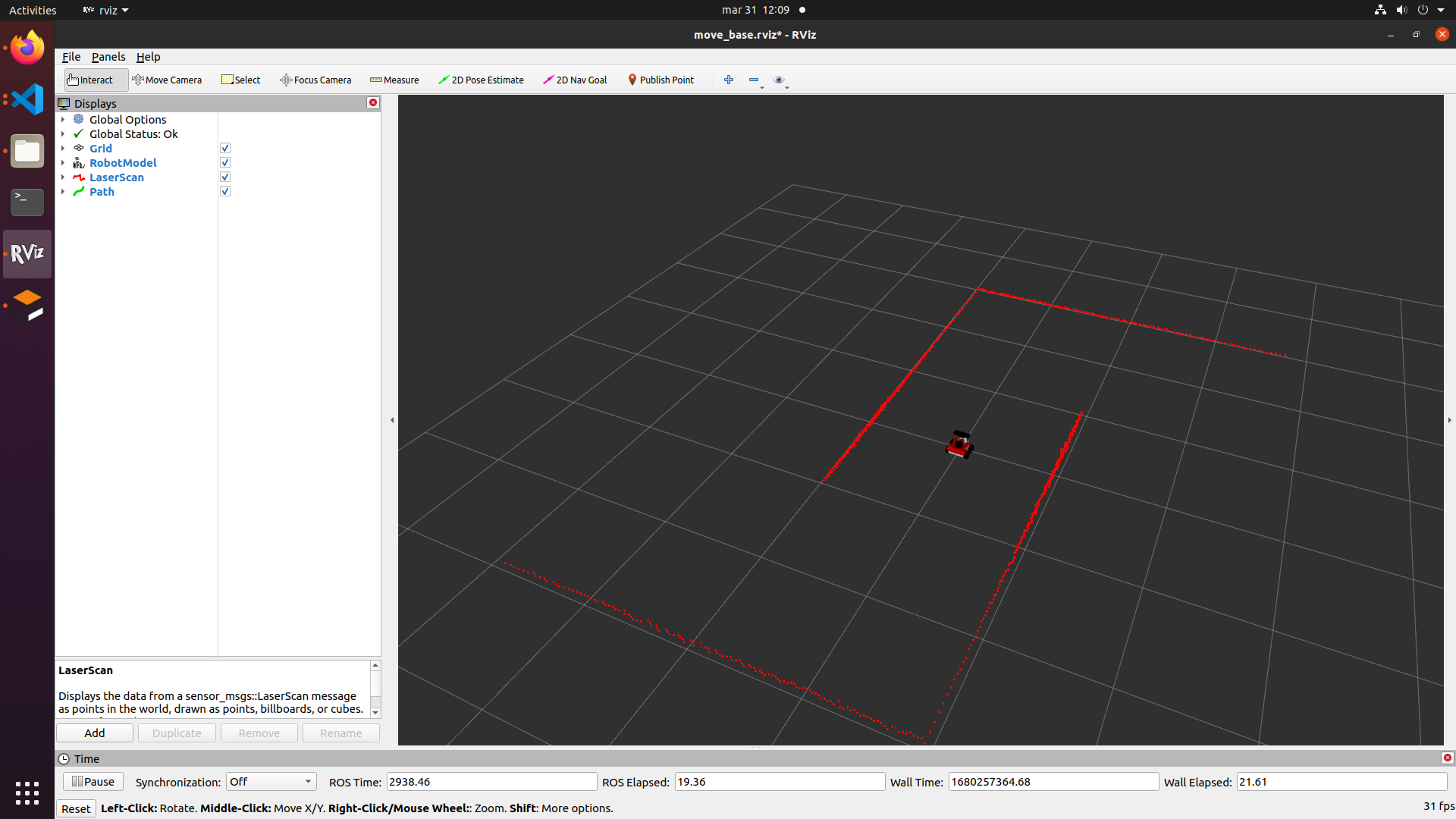
To see results again open RViz and add /scan and also /map topic from By topic tab. Initializing a node can take a while, so you may need to wait few second until you see generated map. Starting state should be similar to below picture:
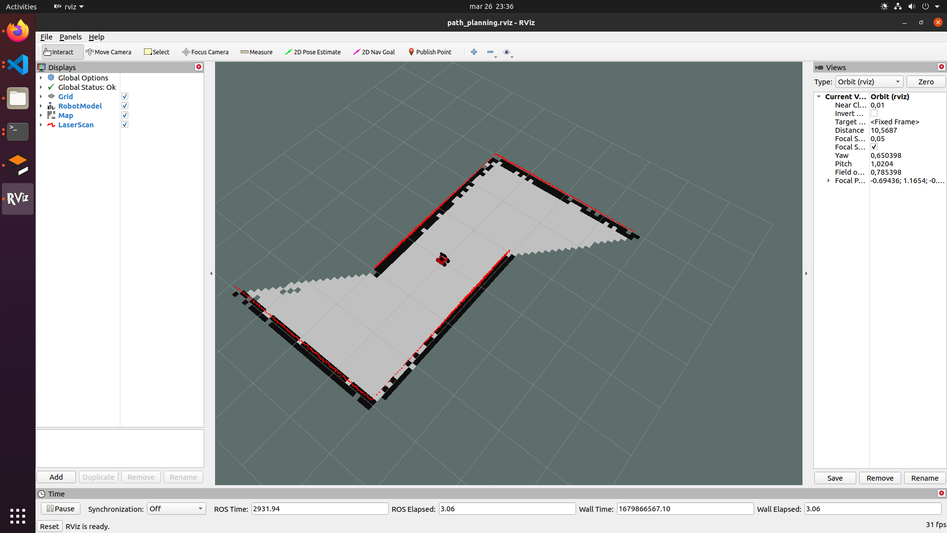
Now drive your robot around and observe as new parts of map are added, continue until all places are explored. Final map should look like below:
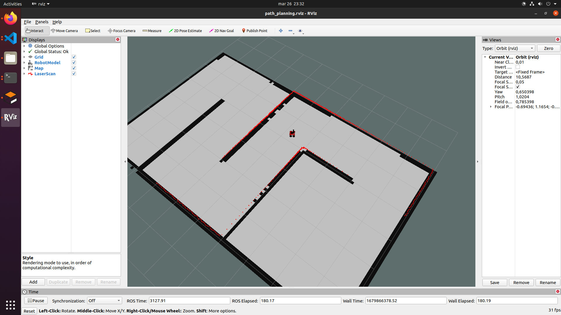
In this way, a occupancy map was created, where white points indicate free space, black points are a wall or other obstacle, and transparently marked places not yet visited. More about the occupancy map can be found in the next chapter - path planning. Now let's learn how to save the map.
Saving the map
SLAM based on for instance gmapping works this way that localization and map is available till node is running, when you close your node you will lose all your explored map. To deal with this we can save map, this is done by map_server , map server is package providing all needed nodes for managing map.
Once map is explored open another terminal and type below lines to save our map in tutorial_pkg/maps.
roscd tutorial_pkg
mkdir maps && cd maps
rosrun map_server map_saver -f map
This command saves map under current working directory with name specified after -f param. After executing this command you should have two files in the indicated directory map.pgm and map.yaml. File map.yaml contains all information about this map and it should look as follows:
image: map.pgm
resolution: 0.050000
origin: [-100.000000, -100.000000, 0.000000]
negate: 0
occupied_thresh: 0.65
free_thresh: 0.196
The code explained
image- path to the image file containing the occupancy data; can be absolute, or relative to the location of the YAML file.resolution- resolution of the map, meters / pixel.origin- 2-D pose of the lower-left pixel in the map, as (x, y, yaw), with yaw as counterclockwise rotation (yaw=0 means no rotation).negate- reverses the black and white colors (it does not affect the interpretation of thresholds).occupied_thresh- pixels with a value greater than this threshold are considered fully occupied.free_thresh- pixels below this threshold are considered completely free.
Map loading
The map_server node is used to load maps. It can be started in 2 ways. Using the rosrun command:
rosrun map_server map_server map.yaml
or using launch file:
<arg name="map_name" default="map.yaml"/>
<node name="map_server" pkg="map_server" type="map_server" args="$(find tutorial_pkg)/maps/$(arg map_name)" respawn="true" />
Localize robot with amcl
AMCL is a probabilistic 2D moving robot location system. It implements an adaptive (or KLD sampling) Monte Carlo location approach (described by Dieter Fox) that uses a particle filter to track the position of the robot on a known map.
Basically amcl is no longer a SLAM algorithm because it does not map the environment. However, the principle of operation of the locator can be helpful to better understand the SLAM group of algorithms. For the algorithm to work properly, it must have access to the map and odometry data. With this data, the algorithm of each iteration compares the appearance of the map, along with the current laser scans, and selects only those locations that best match the collected data with the map.
Run localization
Create launch file for AMCL based on params we have discussed, and save it under launch directory and name localization.launch :
<launch>

  <arg name="use_gazebo" default="false" />
  <arg name="map_name" default="map.yaml"/>

  <!-- Gazebo -->
  <group if="$(arg use_gazebo)">
      <param name="use_sim_time" value="true" />
      <include file="$(find rosbot_bringup)/launch/rosbot_tutorial.launch">
          <arg name="world" value="maze" />
      </include>
  </group>

  <!-- Load map -->
  <node name="map_server" pkg="map_server" type="map_server" args="$(find tutorial_pkg)/maps/$(arg map_name)" respawn="true" />

  <!-- AMCL localizer -->
  <node pkg="amcl" type="amcl" name="amcl" output="screen">
    <param name="odom_frame_id" value="odom"/>
    <param name="odom_model_type" value="diff-corrected"/>
    <param name="base_frame_id" value="base_link"/>
    <param name="update_min_d" value="0.1"/>
    <param name="update_min_a" value="0.2"/>
    <param name="min_particles" value="100"/>
    <param name="global_frame_id" value="map"/>
    <param name="tf_broadcast" value="true" />
    <param name="initial_pose_x" value="0.0"/>
    <param name="initial_pose_y" value="0.0"/>
    <param name="initial_pose_a" value="0.0"/>
  </node>

  <!-- Teleoperation - keyboard control -->
  <node pkg="teleop_twist_keyboard" type="teleop_twist_keyboard.py" name="teleop_twist_keyboard" output="screen"/>

</launch>
The code explainer
There are many parameters provided by the AMCL node, we will focus on the most important ones (the others can be found in the amcl documentation).
global_frame_id- Frame name of global frame, usually it's mapodom_frame_id- Frame name of odom.base_frame_id- Frame name of base.odom_model_type- Method of how your navigates options are diff/omni ,but use fixed algorithms with -corrected suffix. Example: "diff-corrected".update_min_d- minimal translational movement required before performing a filter update.update_min_a- minimal rotational movement required before performing a filter update.min_particles- Minimum allowed number of particles. How many of laser scan points is used to estimate position, if you have changing environment consider enlarging this param.tf_broadcast- Decide if publish the transform between the global frame and the odometry frame.initial_pose_x,initial_pose_y&initial_pose_a- Initial pose of robot (x,y,yaw) coordinates, you should set this param different than "0.0" only if place where robot starts navigation is different than start point for map. If it's small distance you should leave this as "0.0".
To run SLAM example type:
- ROSbot
- Gazebo simulator
docker compose up -d rosbot ros-master rplidar
roslaunch tutorial_pkg localization.launch
roslaunch tutorial_pkg localization.launch use_gazebo:=true
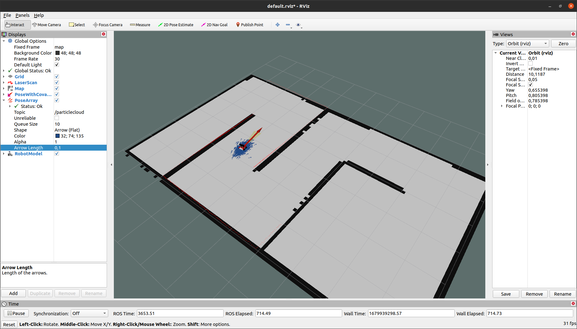
Open RViz and add topics: /scan, /map, /amcl_pose, /partice_cloud and also RobotModel. You can change size and color of /partice_cloud to better visibility. As a result, you should get a result similar to the image below, where each arrow represents the position of the robot.
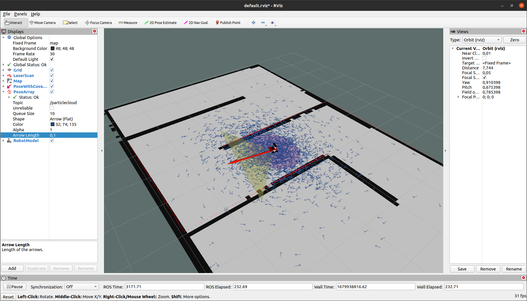
When you move you can observe that your you can see your position converge to your actual position.
Initial Pose
When locating, it is a good idea to set the home position close to the actual position of the robot, otherwise the robot may never find the correct position. It is possible to change the current position of the robot, to do this in RViz, use 2D Estimate Pose and select a point on the map close to the current position of the robot. If the indicated position is slightly away from the current position, the algorithm will automatically improve the quality of the position after driving a few meters.
Task 1
Set an inaccurate initial position of the robot and observe what happens. You should get a similar result as below.
Summary
After completing this tutorial, the concept of SLAM should no longer be foreign to you. From now on, you should know how to run rpLidar and know how to create a map, save it, and fix a location using amcl. Moreover, you should know how to change the slam_gmapping, map_server and amcl parameters. That's all for now and see you in the next tutorial! 😁
by Łukasz Mitka, Adam Krawczyk, Rafał Górecki, Husarion
Need help with this article or experiencing issues with software or hardware? 🤔
- Feel free to share your thoughts and questions on our Community Forum. 💬
- To contact service support, please use our dedicated Issue Form. 📝
- Alternatively, you can also contact our support team directly at: support@husarion.com. 📧