Visual Object Recognition
Chapter description
In this tutorial, we will return to the subject of the camera. We will learn a simple tool that allows you to quickly learn about patterns in an image and use it to perform simple actions. Then we will modify the code a bit so that the robot will be able to follow the recognized object. Time-of-Flight distance sensors will be used to track the detected object. As image processing is quite computationally complex, the speed of the algorithm will be low. There's no need to worry about that because in the next chapter we'll show an example of how to speed up processing by transferring it to our local hardware.
You can run this tutorial on:
Repository containing the final effect after doing all the ROS Tutorials you can find here
We have also prepared ready to go virtual environment with end effect of following this tutorial. It is available on ROSDS:

Introduction
Objects can be recognized by the robot using a vision system. The algorithm will detect the characteristic features of the image, such as points, lines, edge colors and their relative position.
Object recognition processing consists of two steps. The first is training and should be done before the main operation of the robot. During this stage, the object of interest is presented to the vision system, and the algorithm automatically collects a set of features. This data is stored sequentially as a pattern.
The second stage is actual recognition, which is performed continuously while the robot is running. Each frame from the camera is processed, image features are extracted and compared with the data set in memory. If enough features match the pattern, the object is recognized.
In this tutorial we will use the find_object_2d node from the find_object_2d package for both training and recognition.
sudo apt-get install ros-$ROS_DISTRO-find-object-2d
Teaching objects
Anything could be an object to recognize, but remember, that the more edges and contrast colours it has, the easier it will be recognized. A piece of paper with something drawn on it would be enough for this tutorial.
To run this tutorial you should be familiar with the topic of starting the camera. Based on this knowledge we create new launch file, which contains Gazebo or astra camera launching command and newly installed find_object_2d. Node find_object_2d by default subscribe to /image topic, so we need to remap it to our topic /camera/rgb/image_raw.
You should create new image_recognition.launch file can use below launch file:
<launch>

    <arg name="use_gazebo" default="false" />
    <arg name="teach" default="false"/>

    <!-- Gazebo -->
    <group if="$(arg use_gazebo)">
        <param name="use_sim_time" value="true" />
        <include file="$(find rosbot_bringup)/launch/rosbot_tutorial.launch">
            <arg if="$(arg teach)" name="world" value="image_teaching"/>
            <arg unless="$(arg teach)" name="world" value="image_recognition"/>
        </include>
    </group>

    <!-- ROSbot -->
    <group unless="$(arg use_gazebo)">
        <include file="$(find astra_camera)/launch/astra.launch"/>
    </group>

    <!-- Teleoperation - keyboard control -->
    <node name="teleop_twist_keyboard" pkg="teleop_twist_keyboard" type="teleop_twist_keyboard.py" output="screen"/>

    <!-- Object detection -->
    <node pkg="find_object_2d" type="find_object_2d" name="find_object_2d">
        <remap from="image" to="/camera/color/image_raw"/>
        <param name="gui" value="$(arg teach)"/>
        <param unless="$(arg teach)" name="objects_path" value="$(find tutorial_pkg)/img_data/"/>
    </node>

</launch>
Let's start teaching objects:
- ROSbot
- Gazebo simulator
docker compose up -d rosbot ros-master
roslaunch tutorial_pkg image_recognition.launch teach:=true
roslaunch tutorial_pkg image_recognition.launch use_gazebo:=true teach:=true
To place objects in front of camera using Gazebo, you can use buttons Translation mode and Rotation mode in top left corner and drag objects to desired position. Another option is to drive ROSbot to look at the selected object.
After launching the image_recognition.launch file with properly adjusted image topic, new window should appear:
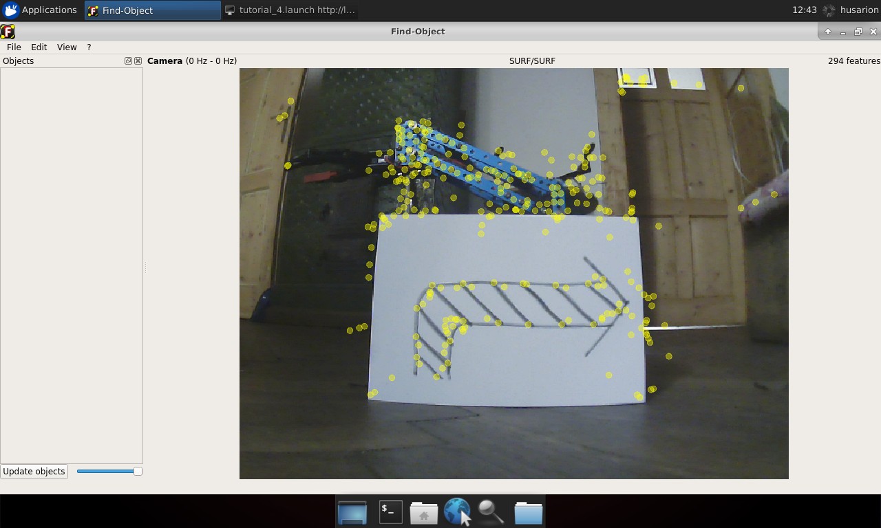
On the left side of the window there are thumbnails of saved images (should be empty at first run). Application main window contains camera view. Yellow circles on the image are marking extracted image features.
To begin teaching process choose from the main toolbar Edit → Add object from scene.... New window will appear. Now move the object and camera in order to cover as many features of the object as possible. While doing that try not to catch object surroundings. When it’s done, click Take picture.
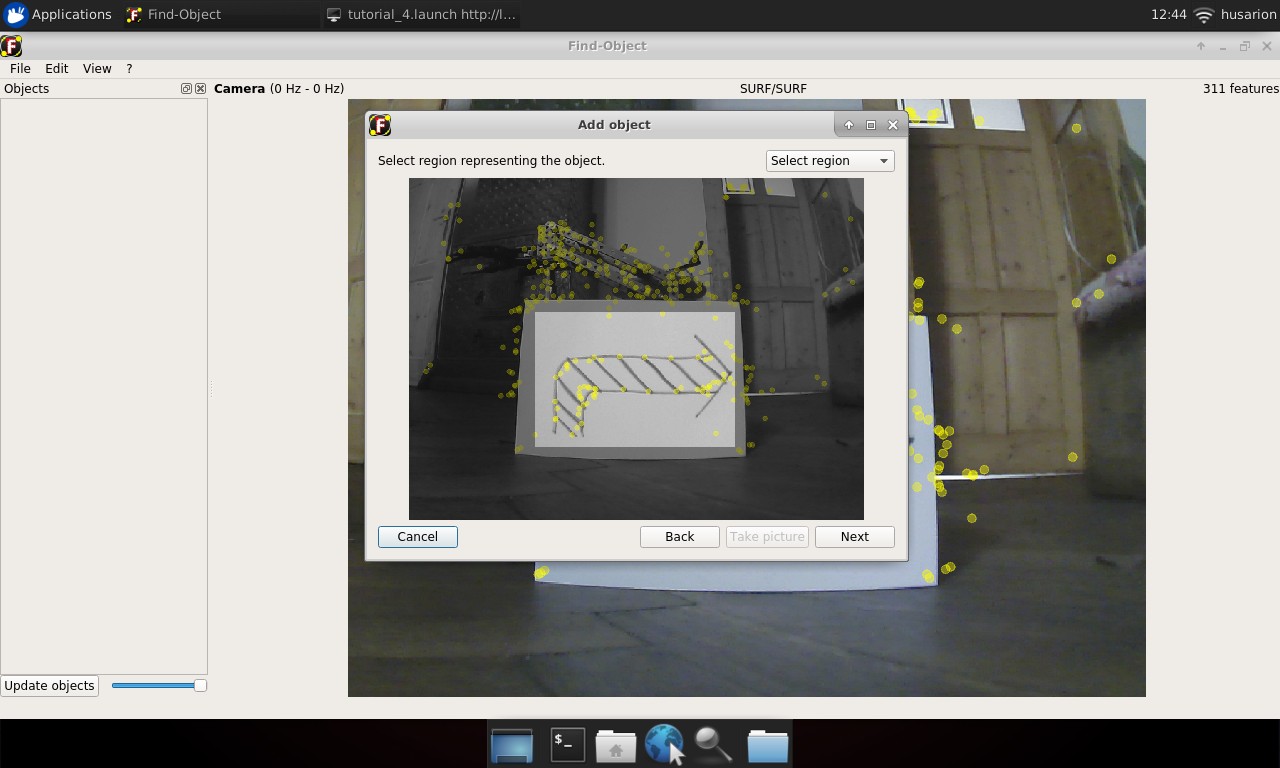
In next view click Select region and select only that part of taken picture, that covers desired object and click Next. You will get confirmation of features extracted from selected image area. If presented image is in accordance with what you selected, click End You should see new thumbnail in the left panel. Notice the number outside of parentheses on the left of the image, this is the object ID.
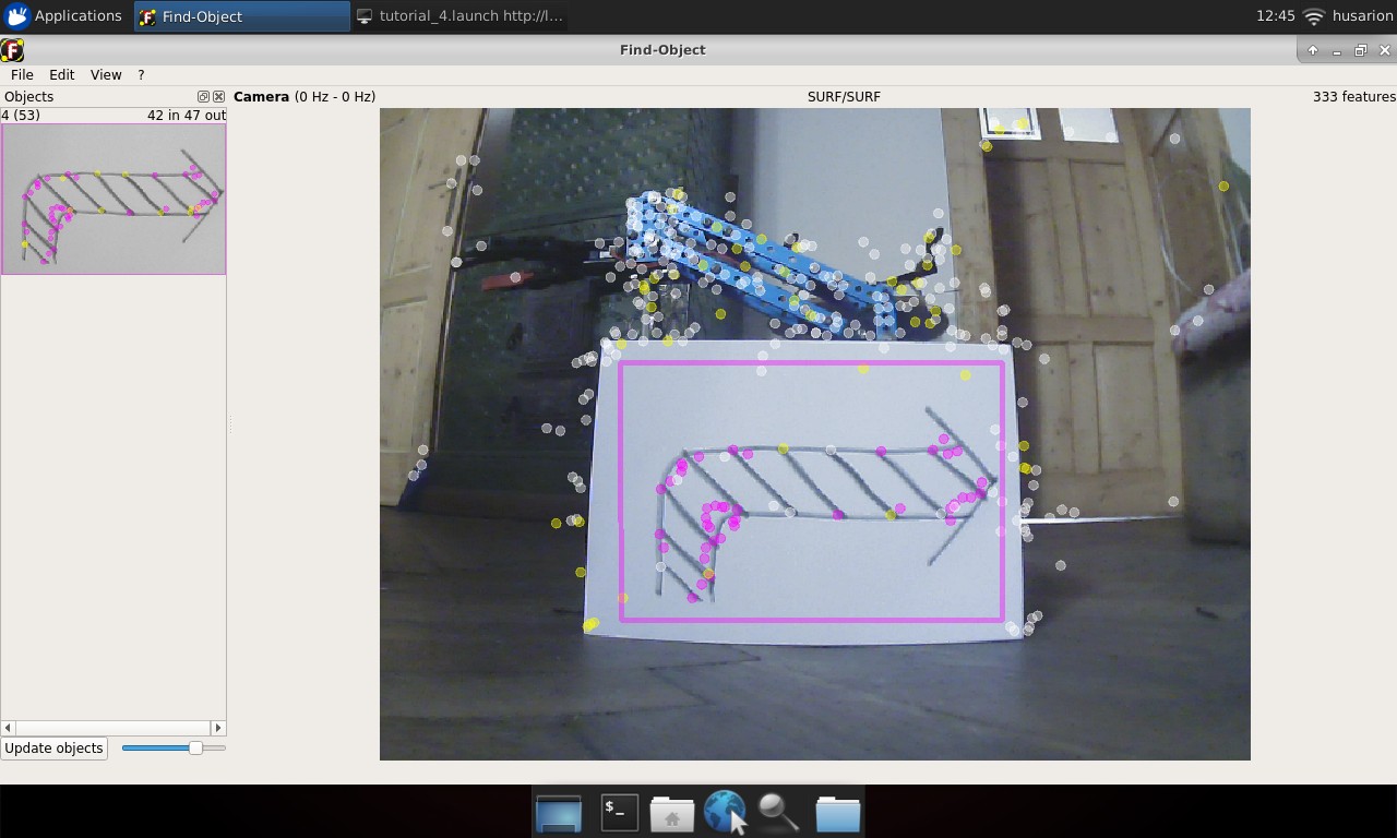
Now you can add some more objects to be recognized. Remember their IDs, you will need them later:
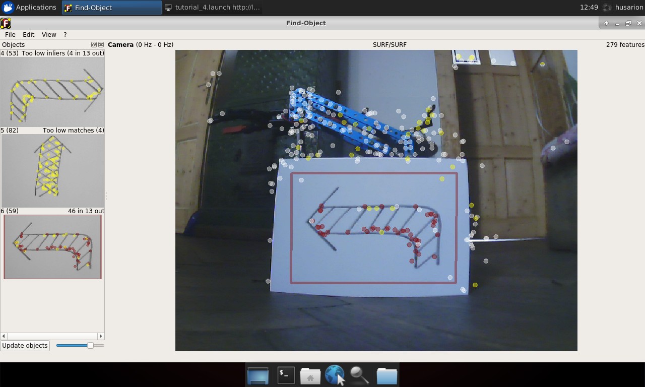
When you have enough objects in the database, you can stop camera Edit → Stop camera and choose from the main toolbar File → Save objects... and save it in ~/ros_ws/src/tutorial_pkg/img_data folder. Now inside this folder you will find all captured objects. Close the window and stop all running nodes.
Recognizing objects
Objects will be recognized by the same find_object_2d node that was used for training, but it works in a slightly different configuration. In the created image_recognition.launch we will set two new parameters for the node. We will set the gui parameter to false, this will run the node without the window to train objects, because we no longer need it. The next parameter will be the objects_path, this should be the path to the folder you just selected to store the recognized objects.
You can use the same launch file without teach parameter to observe the learning results.
- ROSbot
- Gazebo simulator
roslaunch tutorial_pkg image_recognition.launch
roslaunch tutorial_pkg image_recognition.launch use_gazebo:=true
Node is publishing to /objects topic with message type
std_msgs/Float32MultiArray. Data in this message is covering: object
ID, size of recognized object and its orientation. The most interesting
for us is object ID, this is first element of array.
Whenever object is recognized, it will be published in that topic. Place different objects in front of camera and observe as their data is published in the topic.
To watch messages published in the topic, you can use rostopic tool:
rostopic echo /objects
or
rostopic echo /objects/data[0]
to extract only id of recognised item.
Controlling ROSbot using an image
To perform a robot action based on recognized object, we will make a new node. It’s task will be to subscribe /objects topic and publish message to /cmd_vel with speed and direction depending on the object.
Create a new file, name it img_control.cpp and place it in ~\ros_ws\src\tutorial_pkg\srcfolder. Then open it in text editor and paste below code:
#include <ros/ros.h>
#include <std_msgs/Float32MultiArray.h>
#include <geometry_msgs/Twist.h>

// Set value according to your image number in your img_data folder.
#define ARROW_RIGHT 4
#define ARROW_UP 5
#define ARROW_LEFT 6

ros::Publisher vel_pub;
geometry_msgs::Twist vel_msg;

void objectCallback(const std_msgs::Float32MultiArrayPtr &object)
{
    if (object->data.size() > 0){
        int id = object->data[0];

        switch (id){
        case ARROW_RIGHT:
            vel_msg.linear.x = 0;
            vel_msg.angular.z = -1;
            break;
        case ARROW_UP:
            vel_msg.linear.x = 0.5;
            vel_msg.angular.z = 0;
            break;
        case ARROW_LEFT:
            vel_msg.linear.x = 0;
            vel_msg.angular.z = 1;
            break;
        default: // other object
            vel_msg.linear.x = 0;
            vel_msg.angular.z = 0;
        }
    }
    else{
        vel_msg.linear.x = 0;
        vel_msg.angular.z = 0;
    }

    vel_pub.publish(vel_msg);
}

int main(int argc, char **argv)
{
   ros::init(argc, argv, "img_control");
   ros::NodeHandle n("~");
   ros::Rate loop_rate(30);
   ros::Subscriber sub = n.subscribe("/objects", 1, objectCallback);
   vel_pub = n.advertise<geometry_msgs::Twist>("/cmd_vel", 1);
   while (ros::ok())
   {
      ros::spinOnce();
      loop_rate.sleep();
   }
}
The code explained
#include <ros/ros.h>
#include <std_msgs/Float32MultiArray.h>
#include <geometry_msgs/Twist.h>

#define ARROW_RIGHT 4
#define ARROW_UP 5
#define ARROW_LEFT 6
Including required headers and defining constants for recognized objects, adjusting values to IDs of objects recognized by your system. Number should be set according to the name of images in img_data folder:
ros::Publisher vel_pub;
geometry_msgs::Twist vel_msg;
Publisher and message, which will be publishing velocitys:
void objectCallback(const std_msgs::Float32MultiArrayPtr &object) {
Callback function for handling incoming messages with recognized objects data:
if (object->data.size() > 0){
        ...
}
else{
    vel_msg.linear.x = 0;
    vel_msg.angular.z = 0;
}
Checking if size of data field is non zero, if it is, then object is recognized. When data field size is zero, then no object was recognized and we stop the robot.
int id = object->data[0];

switch (id){
case ARROW_RIGHT:
   vel_msg.linear.x = 0;
   vel_msg.angular.z = -1;
   break;
case ARROW_UP:
   vel_msg.linear.x = 0.5;
   vel_msg.angular.z = 0;
   break;
case ARROW_LEFT:
   vel_msg.linear.x = 0;
   vel_msg.angular.z = 1;
   break;
default: // other object
   vel_msg.linear.x = 0;
   vel_msg.angular.z = 0;
}
Reading the recognized object from incoming message and performing the appropriate behavior depending on the recognized object:
vel_pub.publish(vel_msg);
Publishing a new message.
int main(int argc, char **argv)
{
   ros::init(argc, argv, "img_control");
   ros::NodeHandle n("~");
   ros::Rate loop_rate(30);
   ros::Subscriber sub = n.subscribe("/objects", 1, objectCallback);
   vel_pub = n.advertise<geometry_msgs::Twist>("/cmd_vel", 1);
   while (ros::ok())
   {
      ros::spinOnce();
      loop_rate.sleep();
   }
}
Main function, should be already understandable. We initialize node, setting main loop interval, create subscriber to /objects topic and publisher for steering vel_msg. Then we add loop, waiting for trigger messages:
Build code
Last thing to do is editing the CMakeLists.txt file. Find lines:
add_executable(my_first_node src/my_first_node.cpp)

target_link_libraries(my_first_node
    ${catkin_LIBRARIES}
)
and add below code after it:
add_executable(img_control_node src/img_control.cpp)

target_link_libraries(img_control_node
    ${catkin_LIBRARIES}
)
Running your node
Now you can build your node and test it by typing in new terminal.
rosrun tutorial_pkg img_control_node
Getting position of recognized object
Besides the ID of recognized object, find_object_2d node is also publishing a homography matrix of recognized object. In computer vision homography is used to define position of object relative to the camera. We will use it to obtain horizontal position of the object. Homography matrix is published in the same topic as the ID, but in the next cells of data array. They are formatted as
[objectId1, objectWidth, objectHeight, h11, h12, h13, h21, h22, h23, h31, h32, h33, object2].
The next example will be based largely on what has just been shown, so make sure you understand the previous example. Also to do this exercise you need openCV library installed.
Create a new follow_img.cpp file and use the following code.
#include <ros/ros.h>
#include <std_msgs/Float32MultiArray.h>
#include <geometry_msgs/Twist.h>
#include <opencv2/opencv.hpp>

#define OBJECT_TO_FOLLOW 3
#define CAMERA_WIDTH    640 // left 0, right 640

#define MIN_ANG_VEL     0.15f
#define MAX_ANG_VEL     0.5f
#define ANGULAR_GAIN    2e-3 // 0.002 rad/s for each pixel of difference

ros::Publisher vel_pub;
geometry_msgs::Twist vel_msg;

void objectCallback(const std_msgs::Float32MultiArrayPtr &object)
{
    int obj_x_pos;
    float ang_vel;

    // Reset linear and angular speed value
    vel_msg.linear.x = 0;
    vel_msg.angular.z = 0;

    if (object->data.size() > 0){
        int id = object->data[0];
        float objectWidth = object->data[1];
        float objectHeight = object->data[2];

        cv::Mat cvHomography(3, 3, CV_32F);
        std::vector<cv::Point2f> inPts, outPts;
	    switch (id)
        {
        case OBJECT_TO_FOLLOW:

            // Matrix completion
            for(int i=0; i<9; i++){
                cvHomography.at<float>(i%3, i/3) = object->data[i+3];
            }

            // Save corners to vector
            inPts.push_back(cv::Point2f(0, 0));
            inPts.push_back(cv::Point2f(objectWidth, 0));
            inPts.push_back(cv::Point2f(0, objectHeight));
            inPts.push_back(cv::Point2f(objectWidth, objectHeight));
            cv::perspectiveTransform(inPts, outPts, cvHomography);

            obj_x_pos = (outPts.at(0).x + outPts.at(1).x + outPts.at(2).x + outPts.at(3).x) / 4;
            ang_vel = ANGULAR_GAIN*(CAMERA_WIDTH/2 - obj_x_pos);

            // Set angular speed
            if(ang_vel <= -MIN_ANG_VEL || ang_vel >= MIN_ANG_VEL){
                vel_msg.angular.z = std::max(-MAX_ANG_VEL, std::min(ang_vel, MAX_ANG_VEL));
            }
            ROS_INFO("id: %d\t ang_vel: %f", id, vel_msg.angular.z);
            break;
        }
    }

    vel_pub.publish(vel_msg);
}

int main(int argc, char **argv)
{
    ros::init(argc, argv, "follow_obj");
    ros::NodeHandle n("~");
    ros::Subscriber sub = n.subscribe("/objects", 1, objectCallback);
    ros::Rate loop_rate(30);
    vel_pub = n.advertise<geometry_msgs::Twist>("/cmd_vel", 1);
    while (ros::ok())
    {
        ros::spinOnce();
        loop_rate.sleep();
    }
}
The code explained
#include <opencv2/opencv.hpp>
As it was mentioned, the opencv library will be used, so we include it.
#define OBJECT_TO_FOLLOW 3
Select of the object or add new one in the same way as in Teaching objects.
#define CAMERA_WIDTH 640 // left 0, right 640
Define width of camera image. This value will be used to determine horizontal centre pixel.
#define MIN_ANG_VEL     0.15f
#define MAX_ANG_VEL     0.5f
#define ANGULAR_GAIN    2e-3 // 0.002 rad/s for each pixel of difference
Defined some parameters to control rotation speed.
int obj_x_pos;
float ang_vel;
Variable for storing calculated object horizontal centre and angular velocity, based on the difference.
vel_msg.linear.x = 0;
vel_msg.angular.z = 0;
Reset saved information in vel_msg.
float objectWidth = object->data[1];
float objectHeight = object->data[2];
Getting object width and height:
cv::Mat cvHomography(3, 3, CV_32F);
Object for homography matrix:
std::vector<cv::Point2f> inPts, outPts;
Vectors for storing input and output planes:
for(int i=0; i<9; i++){
    cvHomography.at<float>(i%3, i/3) = object->data[i+3];
}
Transfer of coefficients for a homographic matrix.
inPts.push_back(cv::Point2f(0, 0));
inPts.push_back(cv::Point2f(objectWidth, 0));
inPts.push_back(cv::Point2f(0, objectHeight));
inPts.push_back(cv::Point2f(objectWidth, objectHeight));
Defining corners of input plane.
cv::perspectiveTransform(inPts, outPts, cvHomography);
Calculating perspective transformation.
obj_x_pos = (outPts.at(0).x + outPts.at(1).x + outPts.at(2).x + outPts.at(3).x) / 4;
Calculating centre of object from its corners.
ang_vel = ANGULAR_GAIN*(CAMERA_WIDTH/2 - obj_x_pos);

if(ang_vel <= -MIN_ANG_VEL || ang_vel >= MIN_ANG_VEL){
    vel_msg.linear.x = 0;
    vel_msg.angular.z = std::max(-MAX_ANG_VEL, std::min(ang_vel, MAX_ANG_VEL));
}
Calculation of the angular velocity in proportion to the difference between the center of the camera and the horizontal position of the object. It is checked whether the calculated speed is high enough to make the correction. Then the velocity value is subjected to saturation.
Build code
Last thing to do is to edit the CMakeLists.txt file. Now we are using an external OpenCV library, so we need to note this fact in the file.
cmake_minimum_required(VERSION 2.8.3)
project(tutorial_pkg)

add_compile_options(-std=c++11)

find_package(catkin REQUIRED COMPONENTS
  roscpp
)

find_package( OpenCV REQUIRED )

catkin_package(
  CATKIN_DEPENDS
)

include_directories(
    ${catkin_INCLUDE_DIRS}
    ${OpenCV_INCLUDE_DIRS}
)
add_executable(my_first_node src/my_first_node.cpp)
target_link_libraries(my_first_node
  ${catkin_LIBRARIES}
)

add_executable(img_control_node src/img_control.cpp)
target_link_libraries(img_control_node
    ${catkin_LIBRARIES}
)

add_executable(follow_img_node src/follow_img.cpp)
target_link_libraries(follow_img_node
    ${catkin_LIBRARIES}
    ${OpenCV_LIBRARIES}
)
The code explained
find_package( OpenCV REQUIRED )
Specify which other CMake packages that need to be found to build our project. Function find_package generated variable OpenCV_INCLUDE_DIRS, which contains information about necessary directories.
include_directories(
    ${catkin_INCLUDE_DIRS}
    ${OpenCV_INCLUDE_DIRS}
)
Specify where resources can be found.
add_executable(follow_img src/follow_img.cpp)
target_link_libraries(follow_img
    ${catkin_LIBRARIES}
    ${OpenCV_LIBRARIES}
)
Specify the executable target and what libraries the executable target uses (including OpenCV_LIBRARIES).
Running your node
Now you can build your node and test it by typing in new terminal.
rosrun tutorial_pkg follow_img_node
Image processing is quite computationally expensive, so ROSbot can react with a slight delay to a change in the position of the object. In the next tutorial, we will show you how to transfer the calculations from the ROSbot to the other computing device, which will achieve smoother behavior.
Following the object
In the next step, we will modify the above code in such a way that ROSbot will also approach and move away from the object. For the exercise to work properly, the object should be large enough to be detected by the two distance sensors at the front of the vehicle. This exercise will use new information from Time-of-Flight (ToF) sensors. The algorithm will first turn the vehicle so that it is facing the object, then it will move closer or further away to obtain the intended distance.
Let's add few changes in previous file.
#include <ros/ros.h>
#include <std_msgs/Float32MultiArray.h>
#include <geometry_msgs/Twist.h>
#include <opencv2/opencv.hpp>
#include <sensor_msgs/Range.h>

#define OBJECT_TO_FOLLOW 3
#define CAMERA_WIDTH     640 // left 0, right 640

#define MIN_ANG_VEL     0.15f
#define MAX_ANG_VEL     0.5f
#define ANGULAR_GAIN    2e-3 // 0.002 rad/s for each pixel of difference

#define DESIRED_DIST    0.6f
#define MIN_LIN_VEL     0.05f
#define MAX_LIN_VEL     0.4f
#define LINEAR_GAIN     0.4f // 0.4 m/s for each meter of difference


ros::Publisher vel_pub;
geometry_msgs::Twist vel_msg;

float distFL = 0;
float distFR = 0;

void distFL_callback(const sensor_msgs::Range &range)
{
   distFL = range.range;
}

void distFR_callback(const sensor_msgs::Range &range)
{
   distFR = range.range;
}

void objectCallback(const std_msgs::Float32MultiArrayPtr &object)
{
    int obj_x_pos;
    float ang_vel;
    float avg_dist;
    float x_vel;

    // Reset linear and angular speed value
    vel_msg.linear.x = 0;
    vel_msg.angular.z = 0;

    if (object->data.size() > 0){
        int id = object->data[0];
        float objectWidth = object->data[1];
        float objectHeight = object->data[2];

        cv::Mat cvHomography(3, 3, CV_32F);
        std::vector<cv::Point2f> inPts, outPts;
        switch (id)
        {
        case OBJECT_TO_FOLLOW:

            // Matrix completion
            for(int i=0; i<9; i++){
                cvHomography.at<float>(i%3, i/3) = object->data[i+3];
            }

            // Save corners to vector
            inPts.push_back(cv::Point2f(0, 0));
            inPts.push_back(cv::Point2f(objectWidth, 0));
            inPts.push_back(cv::Point2f(0, objectHeight));
            inPts.push_back(cv::Point2f(objectWidth, objectHeight));
            cv::perspectiveTransform(inPts, outPts, cvHomography);

            obj_x_pos = (outPts.at(0).x + outPts.at(1).x + outPts.at(2).x + outPts.at(3).x) / 4;
            ang_vel = ANGULAR_GAIN*(CAMERA_WIDTH/2 - obj_x_pos);

            avg_dist = (distFL + distFR) / 2.0;
            x_vel = LINEAR_GAIN*(avg_dist - DESIRED_DIST);

            // Set angular speed
            if(ang_vel <= -MIN_ANG_VEL || ang_vel >= MIN_ANG_VEL){
                vel_msg.angular.z = std::max(-MAX_ANG_VEL, std::min(ang_vel, MAX_ANG_VEL));
            }
            // Set linear speed
            else if(x_vel <= -MIN_LIN_VEL || x_vel >= MIN_LIN_VEL){
                vel_msg.linear.x = std::max(-MAX_LIN_VEL, std::min(x_vel, MAX_LIN_VEL));
            }
            ROS_INFO("id: %d\t ang_vel: %f\t x_vel: %f", id, vel_msg.angular.z, x_vel);
            break;
        }
    }

    vel_pub.publish(vel_msg);
}

int main(int argc, char **argv)
{
    ros::init(argc, argv, "follow_obj");
    ros::NodeHandle n("~");
    ros::Subscriber sub = n.subscribe("/objects", 1, objectCallback);
    ros::Subscriber distL_sub = n.subscribe("/range/fl", 1, distFL_callback);
    ros::Subscriber distR_sub = n.subscribe("/range/fr", 1, distFR_callback);
    ros::Rate loop_rate(30);
    vel_pub = n.advertise<geometry_msgs::Twist>("/cmd_vel", 1);
    while (ros::ok())
    {
        ros::spinOnce();
        loop_rate.sleep();
    }
}
The code explained
#include <sensor_msgs/Range.h>
Begin with adding new include required header.
#define DESIRED_DIST    0.6f
#define MIN_LIN_VEL     0.05f
#define MAX_LIN_VEL     0.4f
#define LINEAR_GAIN     0.4f // 0.4 m/s for each meter of difference
Defined some parameters to control linear speed.
float distFL = 0;
float distFR = 0;
Add variables for measured object distance.
void distFL_callback(const sensor_msgs::Range &range)
{
   distFL = range.range;
}

void distFR_callback(const sensor_msgs::Range &range)
{
   distFR = range.range;
}
Callback functions for incoming sensor messages, their task is only to put values into appropriate variables.
avg_dist = (distFL + distFR) / 2.0;
x_vel = LINEAR_GAIN*(avg_dist - DESIRED_DIST);
Calculating the linear velocity in a similar way as it was done with the angular velocity.
else if(x_vel <= -MIN_LIN_VEL || x_vel >= MIN_LIN_VEL){
    vel_msg.linear.x = std::max(-MAX_LIN_VEL, std::min(x_vel, MAX_LIN_VEL));
}
Entering the linear speed, provided that the robot is directed at the object and the minimum movement speed is met.
ros::Subscriber distFL_sub = n.subscribe("/range/fl", 1, distFL_callback);
ros::Subscriber distFR_sub = n.subscribe("/range/fr", 1, distFR_callback);
In main function, subscribe to sensor topics.
Running your node
Now you can build your node and test it by typing in new terminal.
rosrun tutorial_pkg follow_img_node
Summary
After completing this tutorial you should be able to configure your ROSbot with vision system to recognize objects. You should also be able to determine the position of recognized object relative to camera and create a node that perform specific action related to recognized objects. You should also know how to handle sensor_msgs/Range message type.
by Łukasz Mitka & Rafał Górecki Husarion
Need help with this article or experiencing issues with software or hardware? 🤔
- Feel free to share your thoughts and questions on our Community Forum. 💬
- To contact service support, please use our dedicated Issue Form. 📝
- Alternatively, you can also contact our support team directly at: support@husarion.com. 📧