ROSbot manipulator collaboration
Abstract
In most industrial cases, application of mobile and manipulation robots significantly speeds up and improves a given process.
Sometimes a combination of the advantages of transport robots and robotic arms is needed to achieve a given goal.
This project, based on ROS2, shows an example of cooperation between the ROSbot 2 PRO mobile robot and a stationary stand composed of the OpenMANIPULATOR-X robotic arm and the Intel Realsense D435 depth camera. The software layer consists of 3 Python nodes (/grabber_from_image_cords, /tracker and /rosbot_control), which are described in ROS Description section.
The full source code is here:
https://github.com/husarion/rosbot-manipulator-collaboration
Description
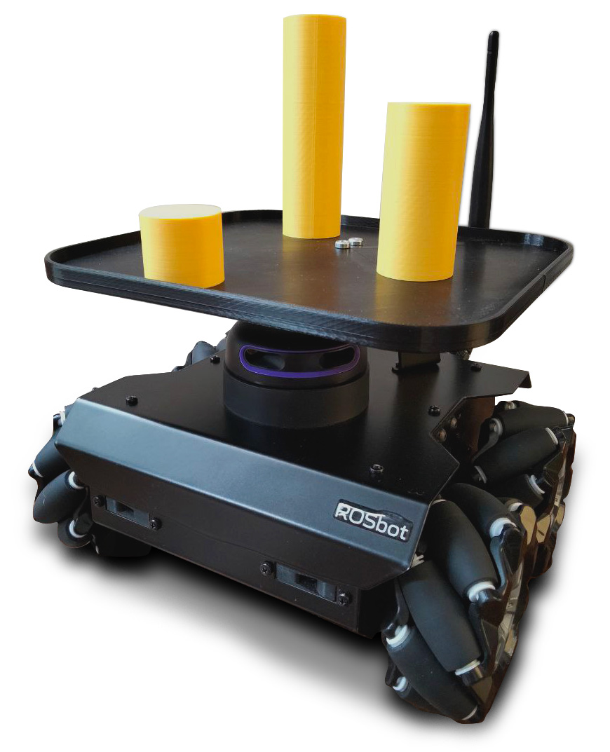
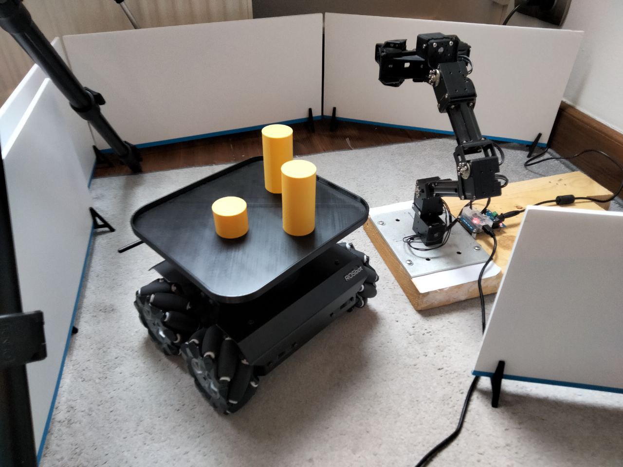
As said in the abstract above, this project is an application based on the cooperation of ROSbot 2 PRO, OpenMANIPULATOR-X and Intel Realsense D435. ROSbot with a custom 3D printed plate transports yellow cylinders (more less with a diameter of 35 mm), which can be also 3D printed, from starting point to the manipulator's area. Above the robotic arm there is a Realsense depth camera which detects the cartesian position of objects and their height. The manipulator picks up the yellow elements one by one putting them on top of each other in a safe place called storage. Then, the empty ROSbot returns to its starting point and waits for new objects to be reloaded in order to start a new sequence.
The final effect of this project can be seen in the video below:
Features and capabilities
- Whole system is Docker-based
- PC / laptop, manipulator and camera communicate with the ROSbot in a Local Area Network (LAN) being in the same Wi-Fi network
- The project is based on autonomous mapping and navigation with ROSbot Navigation2 and Slam Toolbox in Docker
- Application launches Rviz2 software, which shows the visualization of the ROSbot's movement in the room
- Rviz2 also shows images from the camera: color image, depth image and markers on detected objects
- The color of detected objects depends on the HSV ranges set in the code
- System counts collected objects
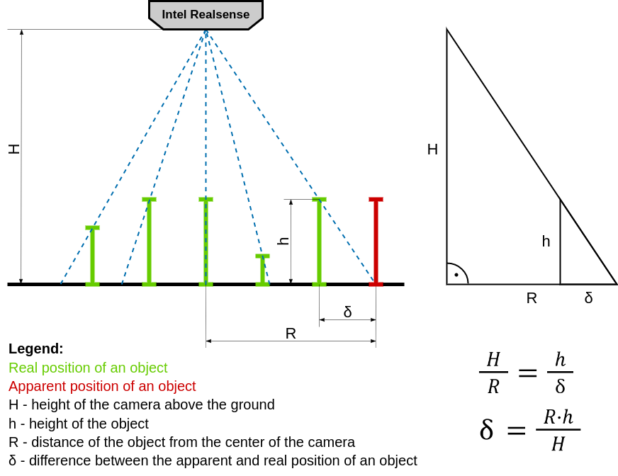
Dealing with parallax error
The camera image is a flat representation of the three-dimensional world. The position of an object in space (the position of its base on the ground) is obtained from the position of its upper surface seen on the image. However, the further away the object is from the center of the image, the more visible it will be from the side. Due to the different height of the objects, its top will no longer reflect the position of its base. In science, this effect has been called "parallax error" and its presence is often marked when reading measurements from analog pointer meters. To compensate it, it is enough to look at the meter directly from above. In the case of this project, the camera is stationary, so a math workaround should be used. Knowing the height (h) of the objects and its distance from the center of the image in XY space (R), you can easily calculate (δ) its real position, getting rid of the parallax error:
ROS Description
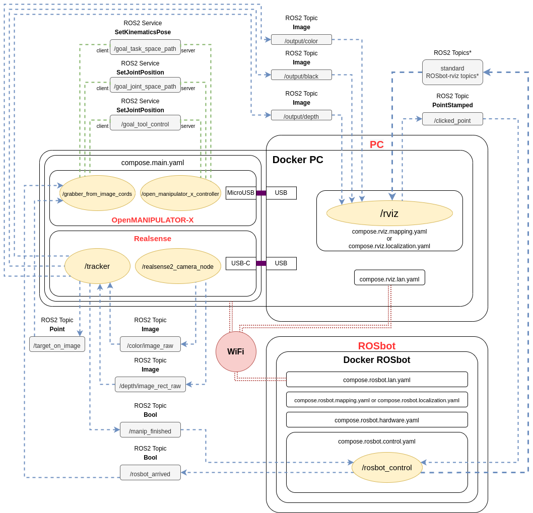
OpenMANIPULATOR launch file offers a lot of services. This project (specifically /grabber_from_image_cords node) uses some of these to control the manipulator: /goal_task_space_path, /goal_joint_space_path, /goal_tool_control.
The realsense node /realsense2_camera_node publishes a lot of topics. This project (specifically /tracker node) uses only two: /color/image_raw and /depth/image_rect_raw.
Rviz2 software shares the feature of publishing data about the point, clicked on the displayed map, on topic: /clicked_point. Node rosbot_control subscribes to that topic.
Also some custom ROS2 Topics were made:
| Topic | Message type | Publisher node name | Description |
|---|---|---|---|
/target_on_image | Point | /tracker | The camera checks for the presence of object(s) and then publishes their XYZ location. |
/output/color | Image | /tracker | Color image from the camera with indication of the detected color |
/output/black | Image | /tracker | Black image with circle(s) graphically highlighting the position(s) of the object(s) |
/output/depth | Image | /tracker | Depth image from the camera |
/manip_finished | Bool | /tracker | The camera checks if the manipulator finished picking object(s) and publishes True of False. |
/rosbot_arrived | Bool | rosbot_control | The ROSbot publishes True upon arrival to the camera and manipulator. |
System schematic diagram:
 * More about topics published by ROSbot to rviz you can find here.
Launching the project
1. Hardware setup
First, print the STL models on your 3D printer.
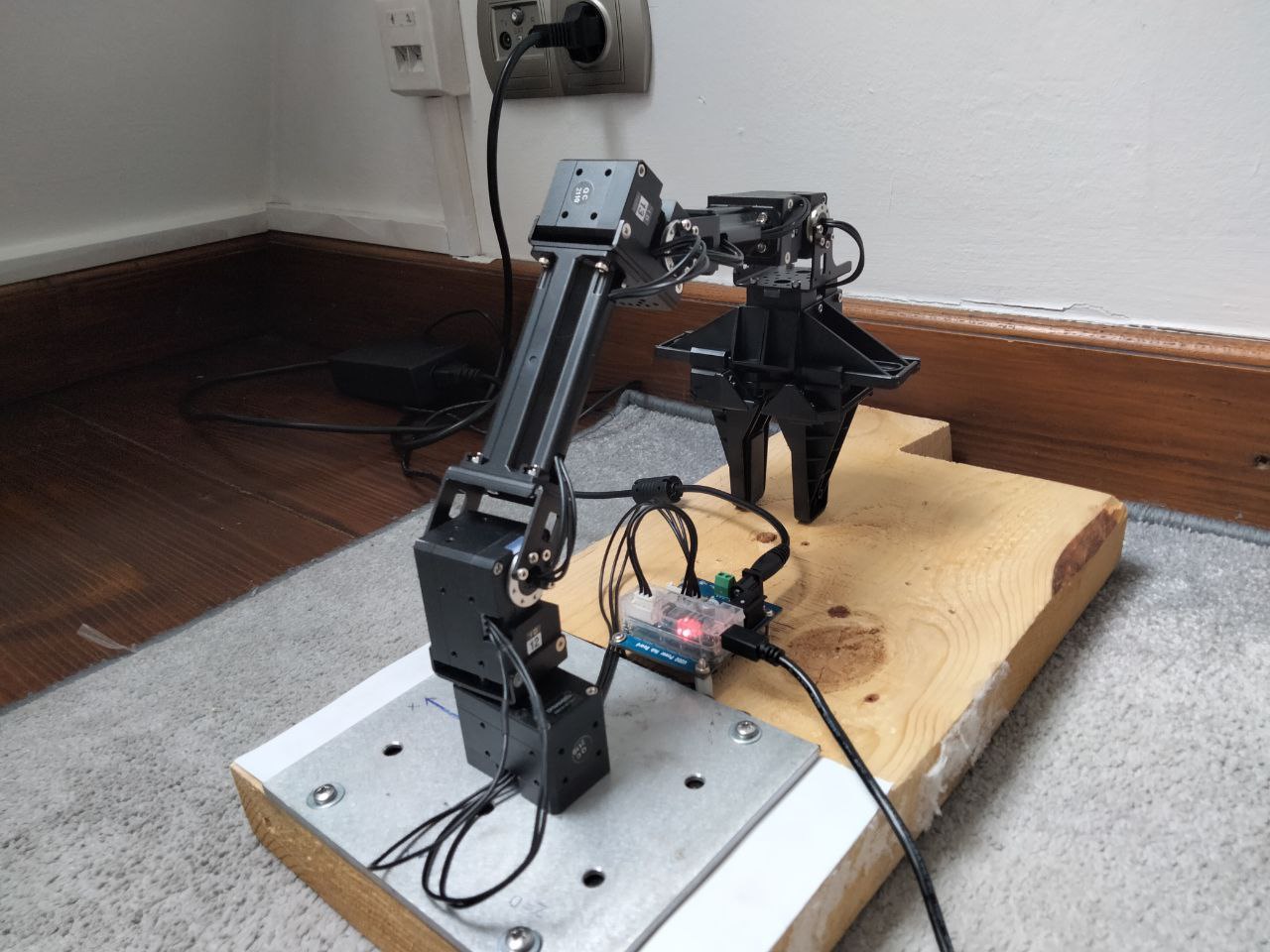
Setup the hardware for example like on photo below. First, set up the tripod (or other similar equipment) with the depth camera pointing directly downwards. Then place the manipulator on a stable base on the ground. It is VERY IMPORTANT that the origin of the manipulator's coordinate system (middle of base of the first servo, the first TF from the ground) is in the middle of the upper border of the color image from the camera. It must be manually precisely set at a later stage of the project, immediately when the color image is displayed.
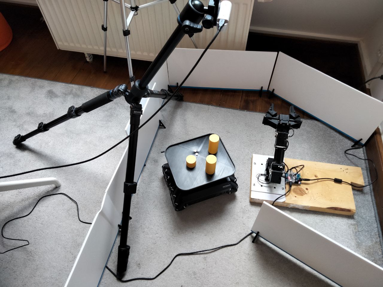
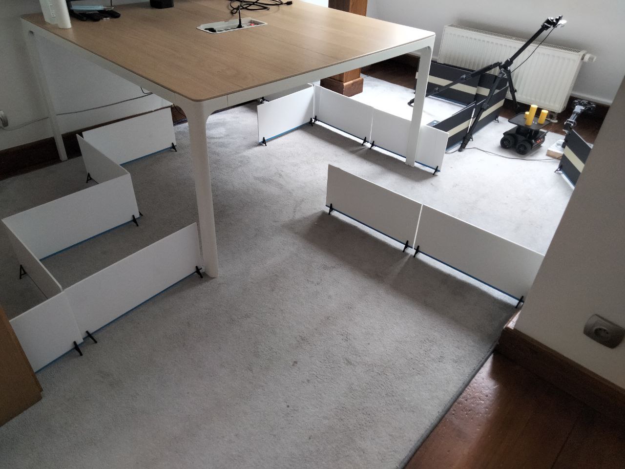
In addition, you can add some obstacles or build small maze:
2. Docker installation
Whole system runs on Docker and Docker-Compose to make it as easy and efficient as possible to launch on different devices. Make sure you have Docker and Docker-Compose installed on your laptop.
If you don't have, here's a quick summary for Ubuntu 20.04 (just click the
copybutton, and paste it to the Linux terminal):Change
/var/run/docker.sockpermissions, so every user can can run docker commands withoutsudo:
3. Connecting to ROSbot via ssh
ROSbot is basically a computer running Ubuntu, so plug in a display with HDMI, mouse and keyboard into the USB port in the rear panel of ROSbot. Proceed step by step with Connecting ROSbot to your Wi-Fi network. For example:
ssh husarion@192.168.8.191
4. Cloning GitHub repository
Both on PC and on ROSbot
Create new folder and clone this repository:
mkdir rosbot_manipulator_collaboration
git clone https://github.com/husarion/rosbot-manipulator-collaboration.git rosbot_manipulator_collaboration
5. Hardcoded variables
Warning To make the project work properly, measure the vertical distance between the camera and the ground using for example the tape measure. The measured value in millimeters should be written into line 25 of:
ros2_ws/src/open_cv_pkg/open_cv_pkg/tracker.pyAnd also the measured value in meters should be written into line 26 of:
ros2_ws/src/open_manip/open_manip/grabber_from_image_cords.pyThen measure the width of the field of view of the camera measured on the ground. The measured value in millimeters should be written into line 28 of:
ros2_ws/src/open_manip/open_manip/grabber_from_image_cords.py
6. Preparing .env file
Navigate to rosbot_manipulator_collaboration/docker_stuff_rosbot/ folder and open .env file with a favorite editor.
For example:
nano .env
Modify its content:
- set your own
ROS_DOMAIN_ID(if modified, write the same inrosbot_manipulator_collaboration/docker_stuff/.env) - set
SERIAL_PORTdepending on what ROSbot you are using - set
RPLIDAR_BAUDRATEdepending on what RPlidar you are using
7. Flash the microcontroller
To flash the right firmware, open ROSbot's terminal (e.g. via ssh) and execute this command:
- for differential drive (regular wheels):
docker run --rm -it --privileged \
husarion/rosbot:noetic \
/flash-firmware.py /root/firmware_diff.bin
- for omnidirectional wheeled ROSbot (mecanum wheels):
docker run --rm -it --privileged \
husarion/rosbot:noetic \
/flash-firmware.py /root/firmware_mecanum.bin
This project is divided into 2 stages: mapping and launching the main project.
Mapping
First you need to map rooms and surroundings with ROSbot and Slam Toolbox. Then save the map. All you need to do is place robot on starting point and:
💻 on PC / laptop:
Navigate to rosbot_manipulator_collaboration/docker_stuff/ folder and execute:
xhost local:root
docker compose -f compose.rviz.mapping.yaml -f compose.rviz.lan.yaml up
🤖 on ROSbot:
Navigate to rosbot_manipulator_collaboration/docker_stuff_rosbot/ folder and execute:
docker compose -f compose.rosbot.hardware.yaml -f compose.rosbot.mapping.yaml -f compose.rosbot.lan.yaml up
Note 💡
In order to use GUI of applications running in containers (like rviz), the
xhost local:rootcommand must be executed on your PC, before starting the containers
Navigate in your room using 2D Goal Pose on Rviz.
When map is finished open new terminal and again connect to ROSBot via ssh like previously.
For example:
ssh husarion@192.168.8.191
Then navigate to rosbot_manipulator_collaboration/docker_stuff_rosbot folder and execute on ROSbot:
./map-save.sh
Your map is now saved in the 'maps/' folder!
Now transfer the maps folder to your laptop using for example sftp. Open a new terminal and execute (with your IP address):
sftp husarion@192.168.8.191
Then execute:
cd rosbot_manipulator_collaboration/docker_stuff_rosbot/
lcd rosbot_manipulator_collaboration/docker_stuff_rosbot/
get -r maps/
Example result of the map:

Mapping phase is completed, you can stop / remove all running containers on ROSbot:
docker kill $(docker ps -q)
docker container prune -f
Launching the main project
The main part of this project is based on the map just created and the localization AMCL tool.
Set your ROSbot on the starting point and put objects on its plate.
💻 on PC / laptop:
Navigate to rosbot_manipulator_collaboration/docker_stuff/ folder and execute:
xhost local:root
docker compose -f compose.main.yaml -f compose.rviz.localization.yaml -f compose.rviz.lan.yaml up
🤖 on ROSbot:
Navigate to rosbot_manipulator_collaboration/docker_stuff_rosbot/ folder and execute:
docker compose -f compose.rosbot.control.yaml -f compose.rosbot.hardware.yaml -f compose.rosbot.localization.yaml -f compose.rosbot.lan.yaml up
Now, using Publish Point on Rviz chose the starting point and the destination point on the loaded map. Everything should look like in previously linked video (go to 4:30):
Possible issues
1. No image from Realsense camera
Every time you stop and restart the project first you need to unplug and plug the USB cable of Realsense.
2. Manipulator doesn't move (controller container exits with error code)
This may be caused by the wrong boudrate of the DYNAMIXEL servos.
There are two ways to solve this problem:
1. Writing Boud Rate directly to your DYNAMIXEL servos
- Download the DYNAMIXEL Wizard 2.0 software and open it.
- Connect the USB cable of the OpenMANIPULATOR-X to your laptop/PC.
- Scan for the servos
- Change their Boud Rate setting in the EEPROM Area to value
2: 115200 [bps]
2. Modify Boud Rate value in compose file to default and hope for the best
Assuming no one has made changes to your servos before, their Boud Rate is set to the default (57600 [bps]).
Modify the line 17 of the rosbot_manipulator_collaboration/docker_stuff/compose.main.yaml file:
From:
17 command: ros2 launch open_manipulator_x_controller open_manipulator_x_controller.launch.py baud_rate:=115200 # baud_rate:=1000000 or 115200 or none (default 57600)
To:
17 command: ros2 launch open_manipulator_x_controller open_manipulator_x_controller.launch.py # baud_rate:=1000000 or 115200 or none (default 57600)
3. Manipulator doesn't move (controller container runs properly)
There are some positions of the robotic arm which exceed its joint's limits. Try to launch project with the initial pose like this:
Summary
The project of cooperation of the autonomous ROSbot 2 Pro with the manipulator and the depth camera is a demonstration proof of the concept. This basic demo shows how great are the possibilities of collaboration between mobile and manipulation robots based on the ROS 2 environment and the innovative design approach of Husarion robots. We invite you to visit the range of our tutorials and manuals as well as other projects examples.
by Jan Brzyk Husarion
Need help with this article or experiencing issues with software or hardware? 🤔
- Feel free to share your thoughts and questions on our Community Forum. 💬
- To contact service support, please use our dedicated Issue Form. 📝
- Alternatively, you can also contact our support team directly at: support@husarion.com. 📧