ROSbot 3 (and previous 2x versions )
Overview
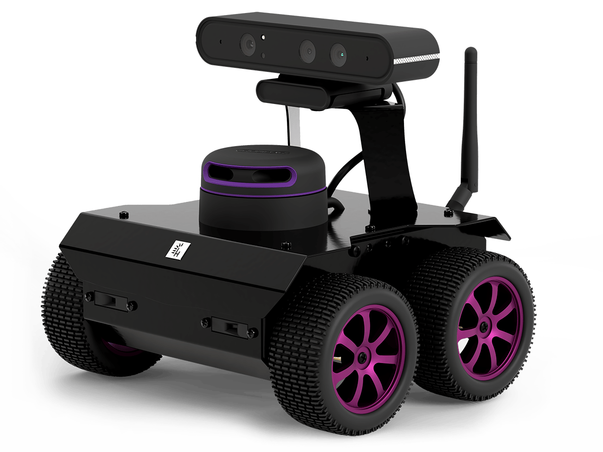
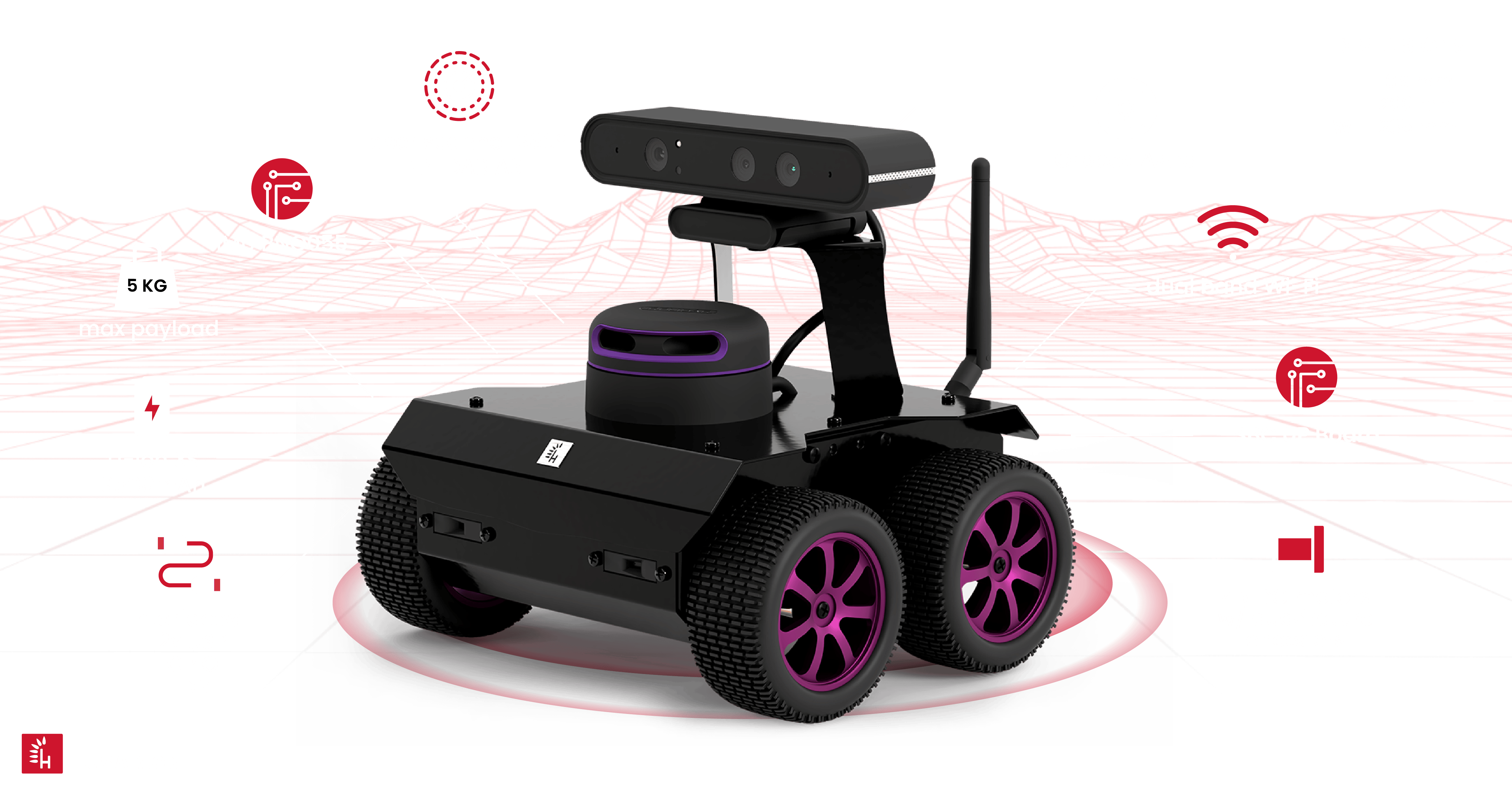
ROSbot is a ROS powered 4x4 drive autonomous mobile robot platform equipped with LIDAR, RGB-D camera, IMU, encoders, distance sensors.
Available in the following versions: 3 / 3 PRO (current version), 2R / 2 PRO (discontinued) and 2 (deprecated).
ROSbot 3 is an affordable robot platform for rapid development of autonomous robots. It can be a base for custom service robots, inspection robots and robots working in swarms. All versions integrate:
- 4-wheels mobile platform containing DC motors with encoders and an aluminum frame
- IMU: BNO055 (accelerometer + gyro)
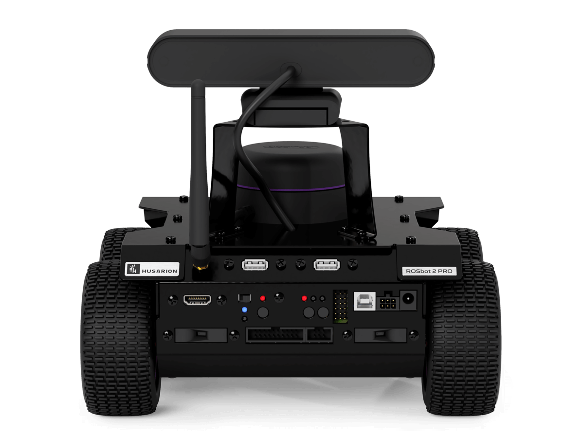
- rear panel providing interfaces for additional modules
ROSbot versions
ROSbot is available in three options which, next to features mentioned before, also include:
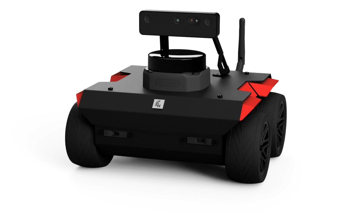
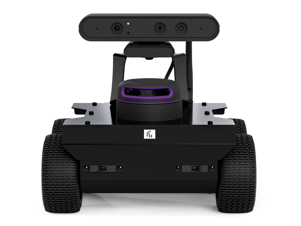
- ROSbot 3 / ROSbot 3 PRO
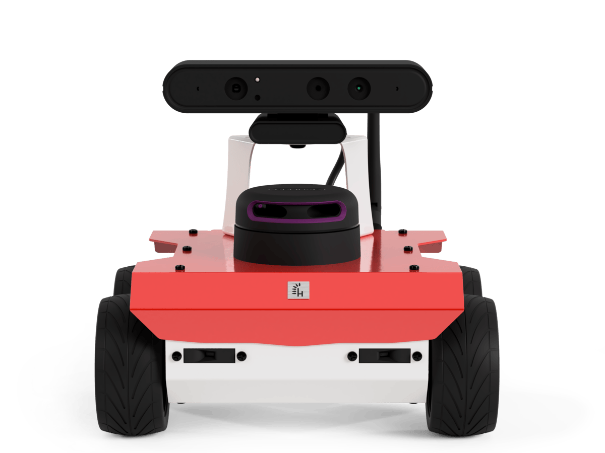
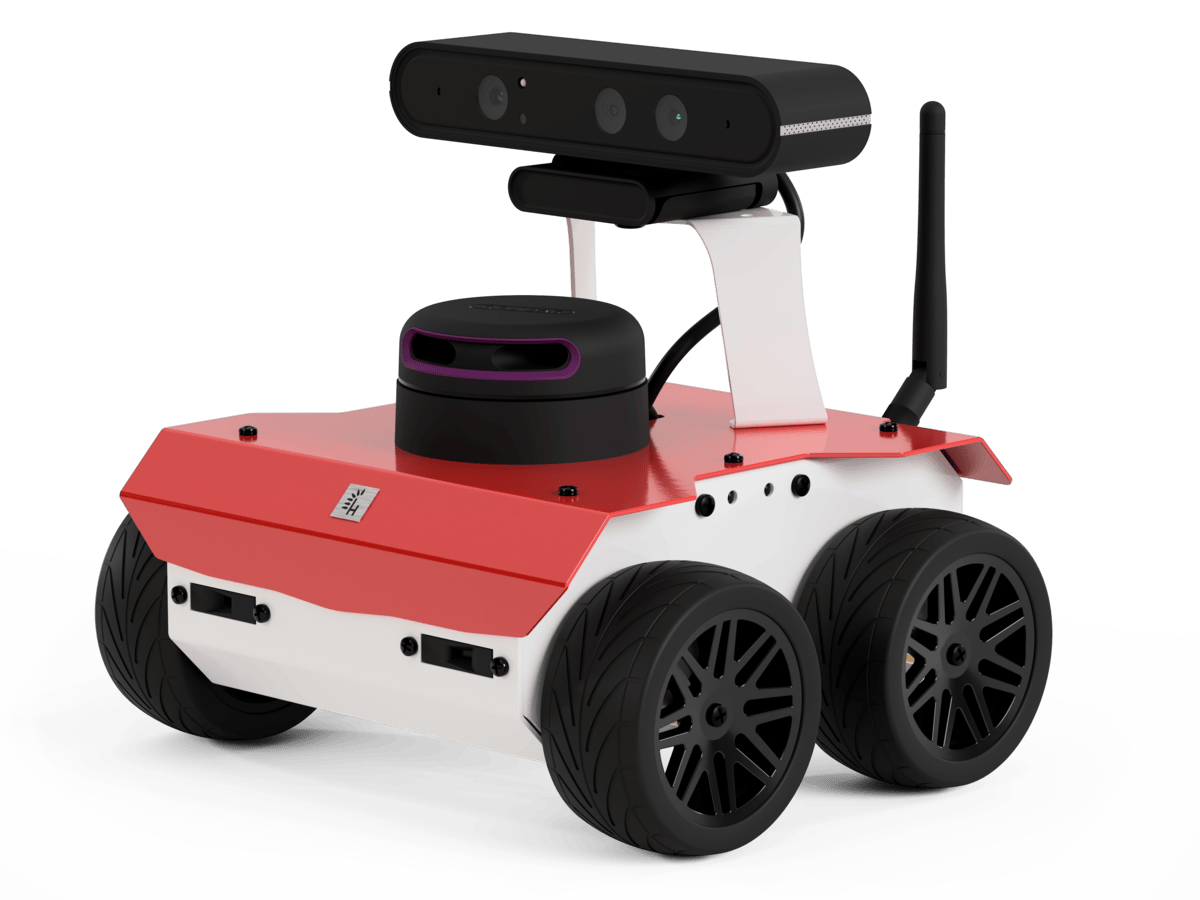
- ROSbot 2R
- ROSbot 2 PRO
- ROSbot 2
- Raspberry Pi 5 (ARM64 architecture) quad-core ARM-8 Cortex A76 @ 2.4GHz, 8GB RAM and 64 GB MicroSD flash memory.
- 3D camera: Luxonis OAK-D Lite / Pro
- LIDAR: RPLIDAR C1 / S2
- Raspberry Pi 4 (ARM64 architecture) quad-core ARM-8 Cortex-A72 @ 1.5 GHz, 4GB RAM and 32 GB MicroSD flash memory.
- 3D camera: Orbbec Astra
- LIDAR: RPLIDAR A2
- UP Board with Intel® ATOM™ x5-Z8350 Processors (x64 architecture) up to 1.92GHz, 4GB DDR3L RAM and 32GB eMMC.
- 3D camera: Orbbec Astra
- LIDAR: RPLIDAR A3
Starting from August 31, 2023 ROSbot 2 (a.k.a. 2.0 / 2.1) will go end-of-life. As of this date, new features won’t be developed for ROSbot 2 and we will no longer be providing support for this model. More information in the announcement.
If you require continued support and advanced capabilities, please consider switching to ROSbot 2R or ROSbot 2 PRO.
- Asus Tinker Board with Rockchip RK3288 (ARM32 architecture) up to 1,8GHz, 2GB DDR3 RAM and 32 GB MicroSD.
- RPLIDAR A2 laser scanner
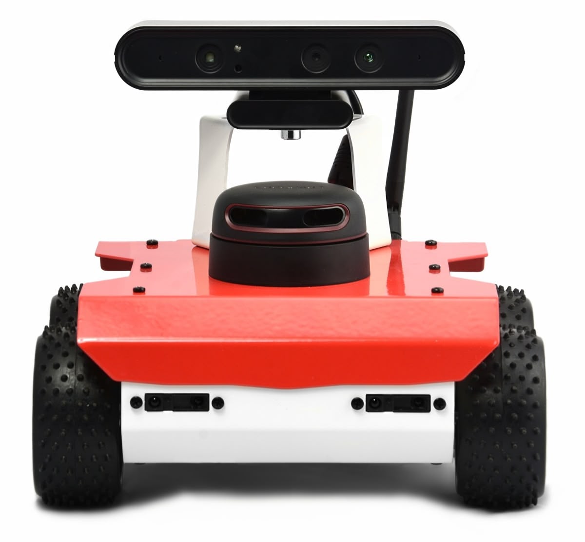
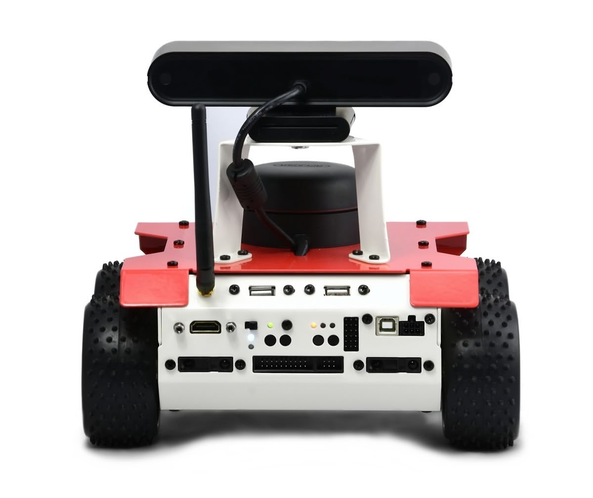
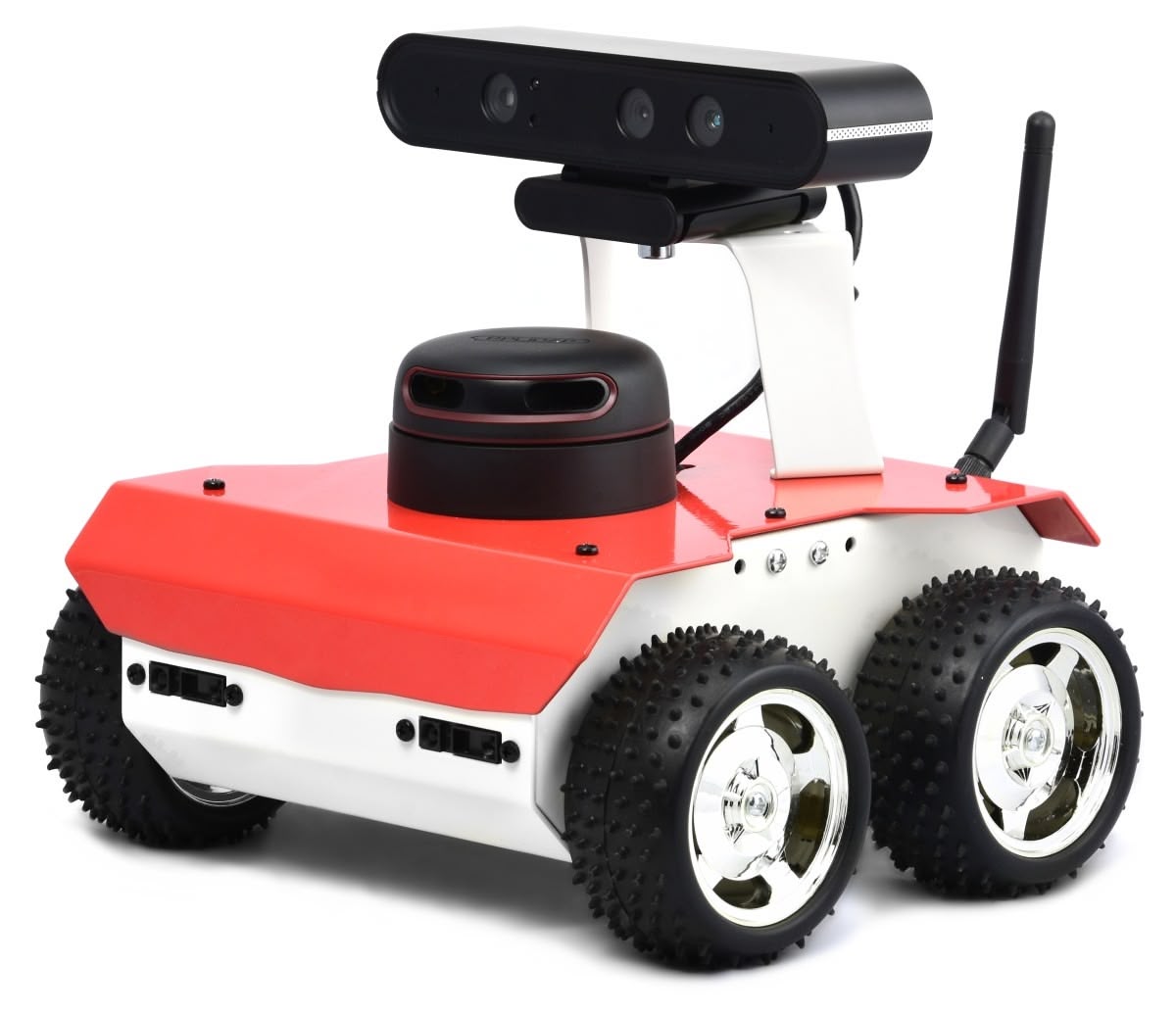
ROSbot 2 is discontinued, but you can get its new generation - ROSbot 2R - available here.
Gazebo Simulation Model
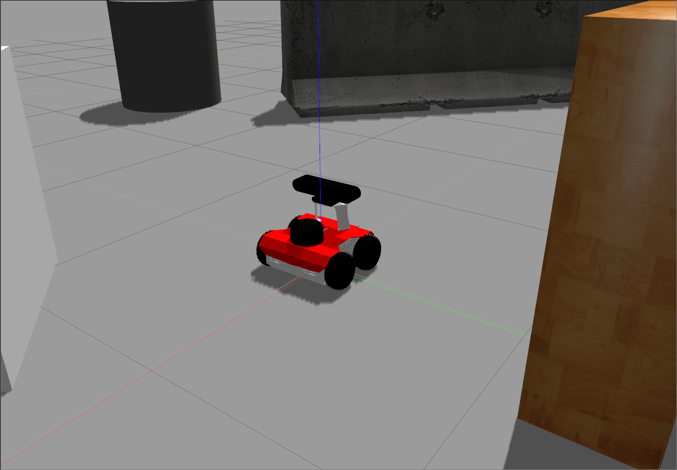
You can also test the performance of ROSbot using our simulation model in Gazebo environment. It is available here, at our GitHub page.
You can find free ROS tutorials dedicated for ROSbot under this link. They will guide you through different aspects of programming autonomous vehicles in ROS
Hardware guide
Specification
- ROSbot 3 / ROSbot 3 PRO
- ROSbot 2R
- ROSbot 2 PRO
- ROSbot 2
| Attribute | Description |
|---|---|
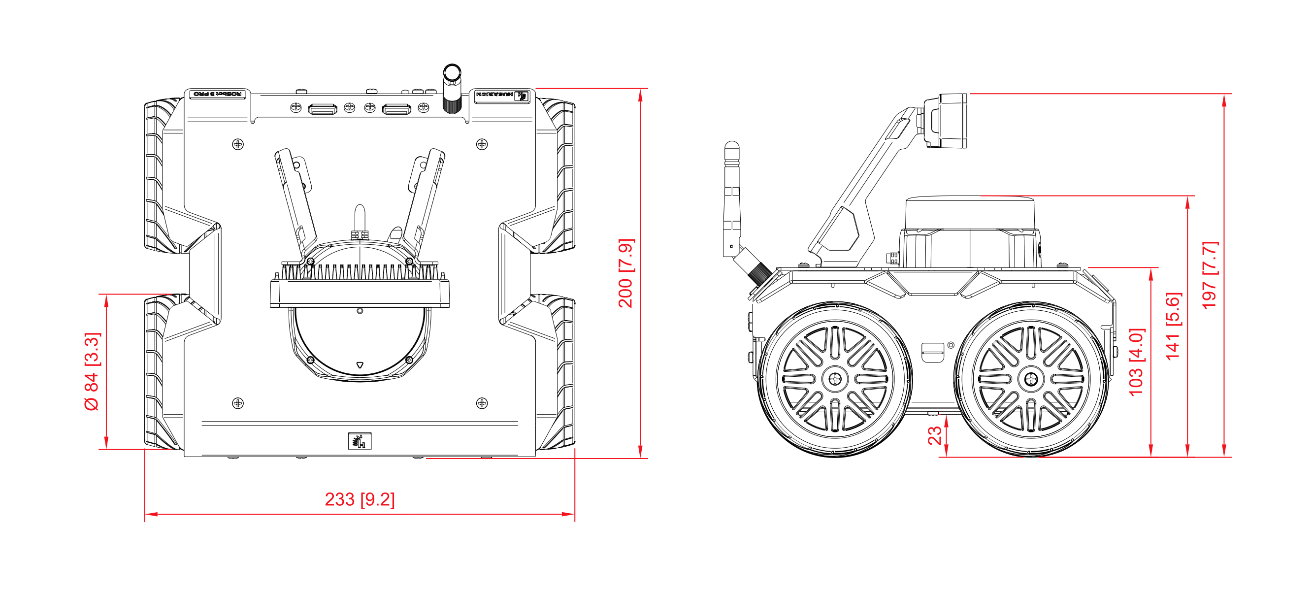
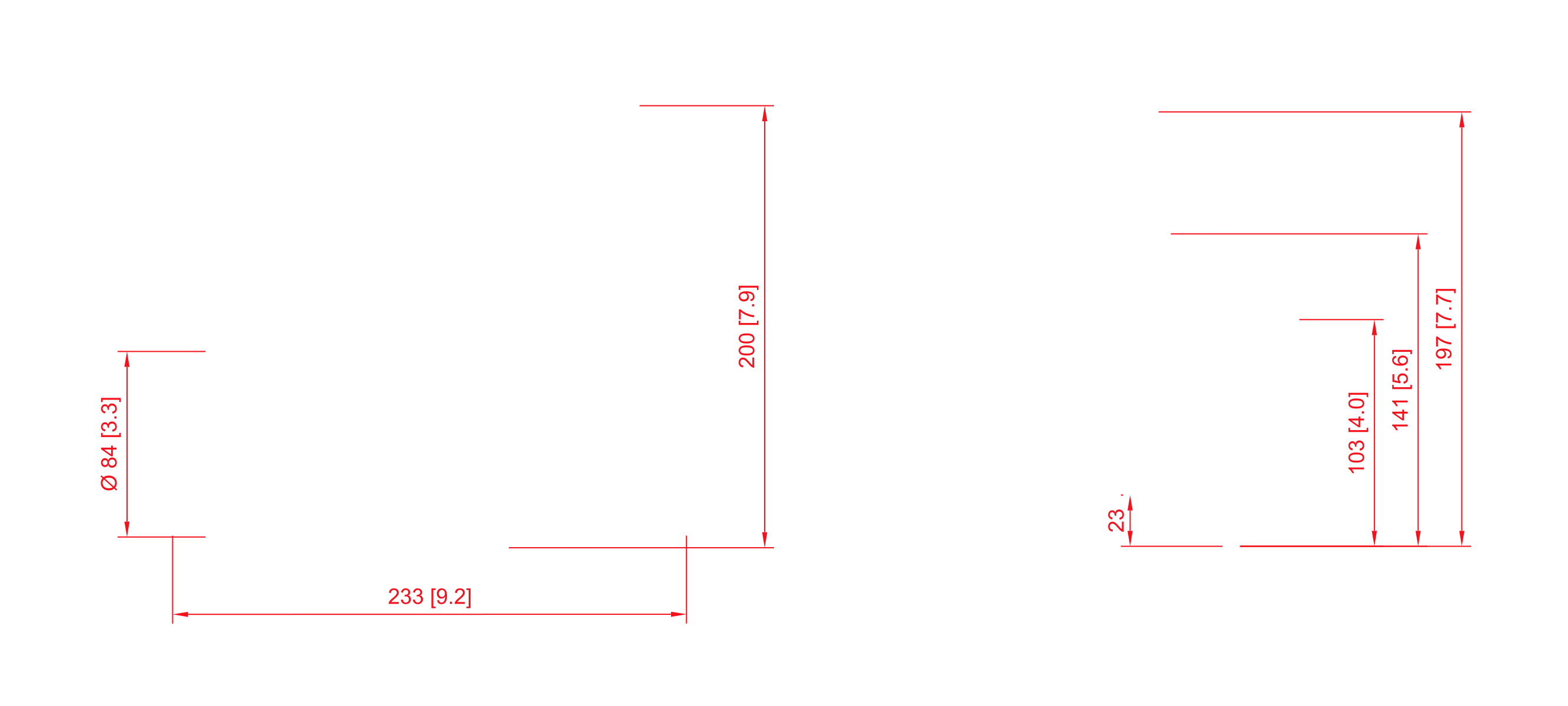
| Dimensions with camera and LiDAR | 200 x 233 x 197 mm / 7.9 x 9.2 x 7.7 in [L x W x H] |
| Dimensions without camera | 200 x 233 x 141 mm / 7.9 x 9.2 x 5.6 in [L x W x H] |
| Dimensions without camera and LiDAR | 200 x 233 x 103 mm / 7.9 x 9.2 x 4.0 in [L x W x H] |
| Weight | 2,84 kg / 100 oz (with camera and LiDAR), 2,45 kg / 86 oz (without camera and LiDAR) |
| Standard wheel diameter / Clearance / Wheelbase | 84 mm / 23 mm / 106 mm |
| Mecanum wheel diameter / Clearance / Wheelbase | 97 mm / 30 mm / 106 mm |
| Chassis material | Powder-coated aluminum plate, 1.5 mm thick |
| Maximum translational velocity | 1.0 m/s |
| Maximum rotational velocity | 420 deg/s (7.33 rad/s) |
| Maximum load capacity | Up to 5 kg / 176 oz *not in continuous work |
| Battery life | 1.5h - 5h |
| Attribute | Description |
|---|---|
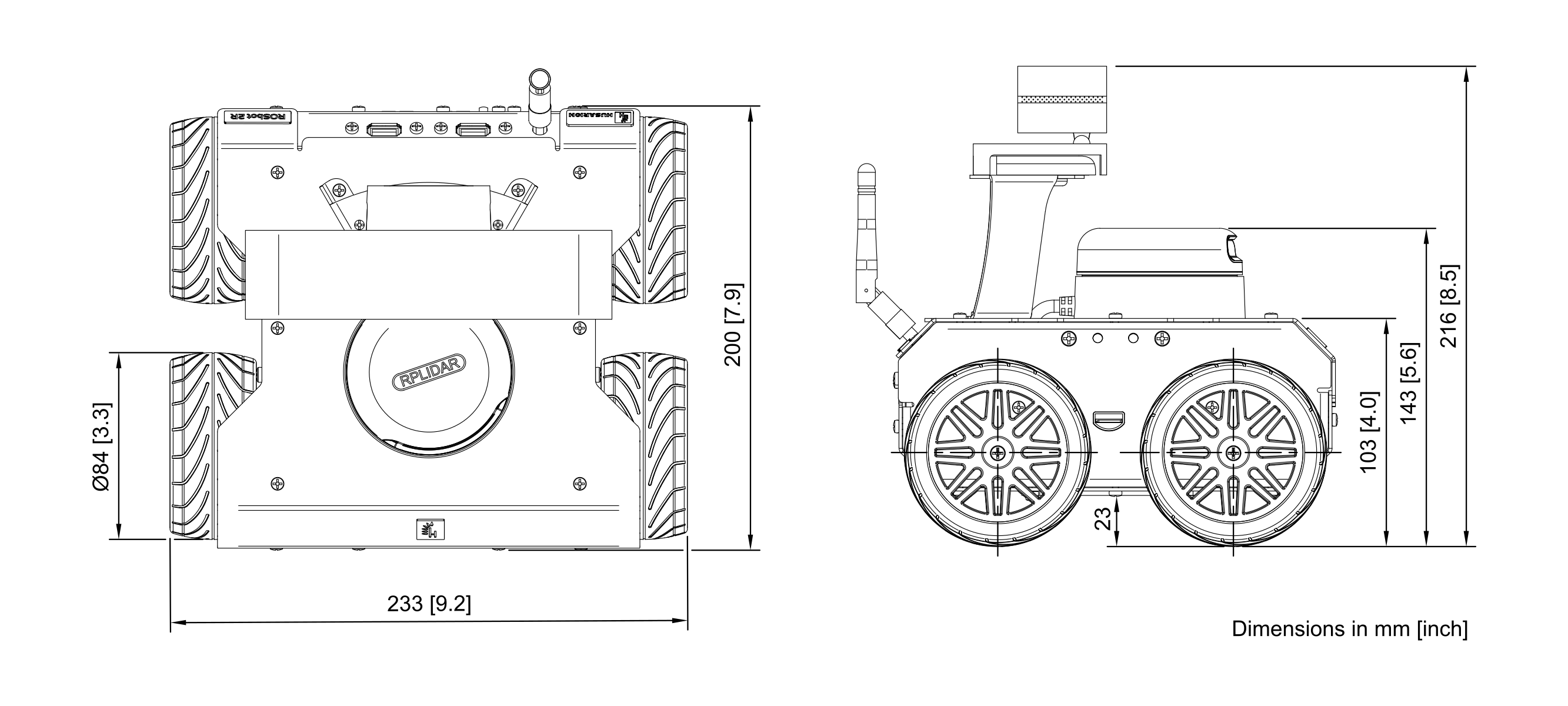
| Dimensions with camera and LiDAR | 200 x 233 x 216 mm / 7.9 x 9.2 x 8.5 in [L x W x H] |
| Dimensions without camera | 200 x 233 x 143 mm / 7.9 x 9.2 x 5.6 in [L x W x H] |
| Dimensions without camera and LiDAR | 200 x 233 x 103 mm / 7.9 x 9.2 x 4.0 in [L x W x H] |
| Weight | 2,84 kg / 100 oz (with camera and LiDAR), 2,45 kg / 86 oz (without camera and LiDAR) |
| Standard wheel diameter / Clearance / Wheelbase | 90 mm / 23 mm / 106 mm |
| Mecanum wheel diameter / Clearance / Wheelbase | 100 mm / 30 mm / 106 mm |
| Chassis material | Powder-coated aluminum plate, 1.5 mm thick |
| Maximum translational velocity | 1.0 m/s |
| Maximum rotational velocity | 420 deg/s (7.33 rad/s) |
| Maximum load capacity | Up to 5 kg / 176 oz *not in continuous work |
| Battery life | 1.5h - 5h |
| Attribute | Description |
|---|---|
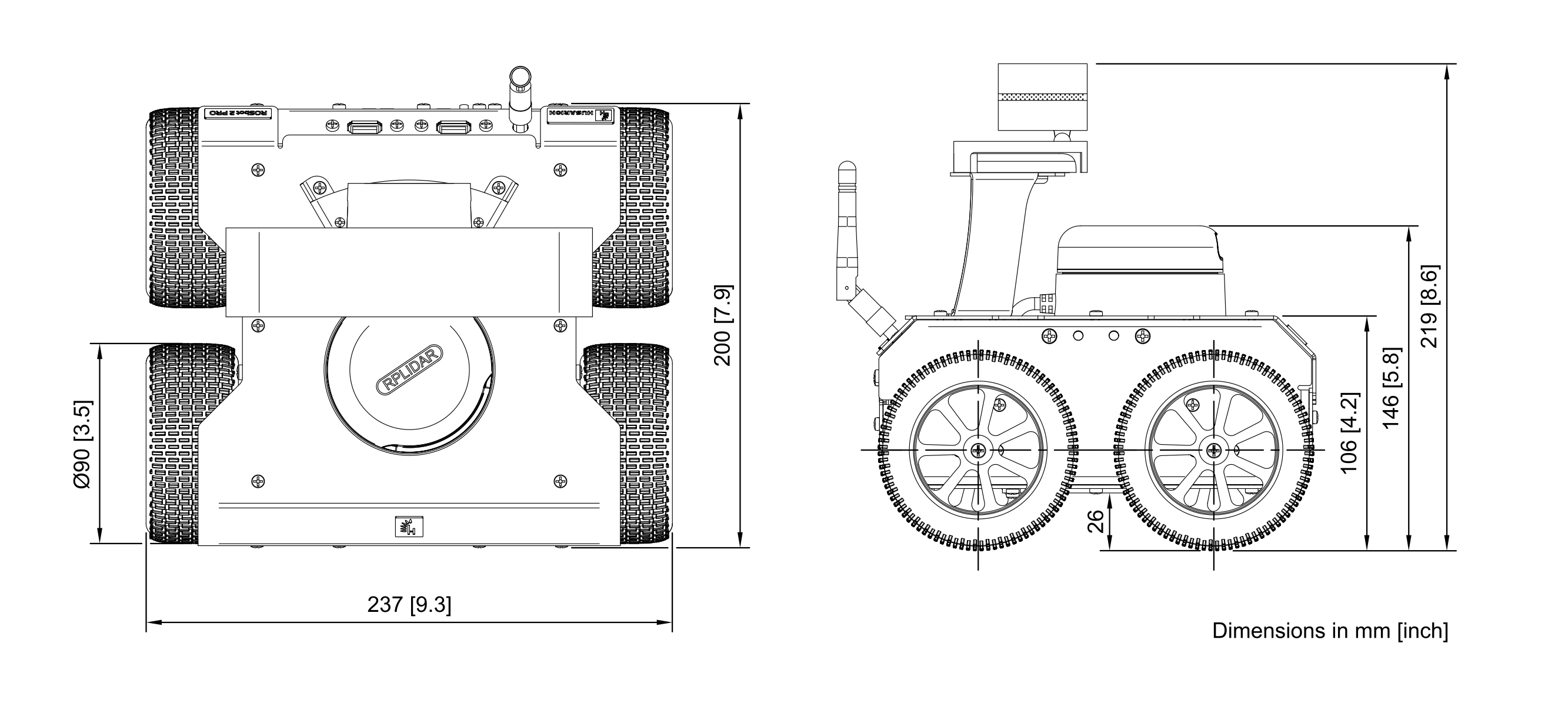
| Dimensions with camera and LiDAR | 200 x 237 x 219 mm / 7.9 x 9.3 x 8.6 in [L x W x H] |
| Dimensions without camera | 200 x 237 x 146 mm / 7.9 x 9.3 x 5.8 in [L x W x H] |
| Dimensions without camera and LiDAR | 200 x 237 x 106 mm / 7.9 x 9.3 x 4.2 in [L x W x H] |
| Weight | 2,84 kg / 100 oz (with camera and LiDAR), 2,45 kg / 86 oz (without camera and LiDAR) |
| Standard wheel diameter / Clearance / Wheelbase | 90 mm / 26 mm / 106 mm |
| Mecanum wheel diameter / Clearance / Wheelbase | 100 mm / 30 mm / 106 mm |
| Chassis material | Powder-coated aluminum plate, 1.5 mm thick |
| Maximum translational velocity | 1.0 m/s |
| Maximum rotational velocity | 420 deg/s (7.33 rad/s) |
| Maximum load capacity | Up to 5 kg / 176 oz *not in continuous work |
| Battery life | 1.5h - 5h |
| Attribute | Description |
|---|---|
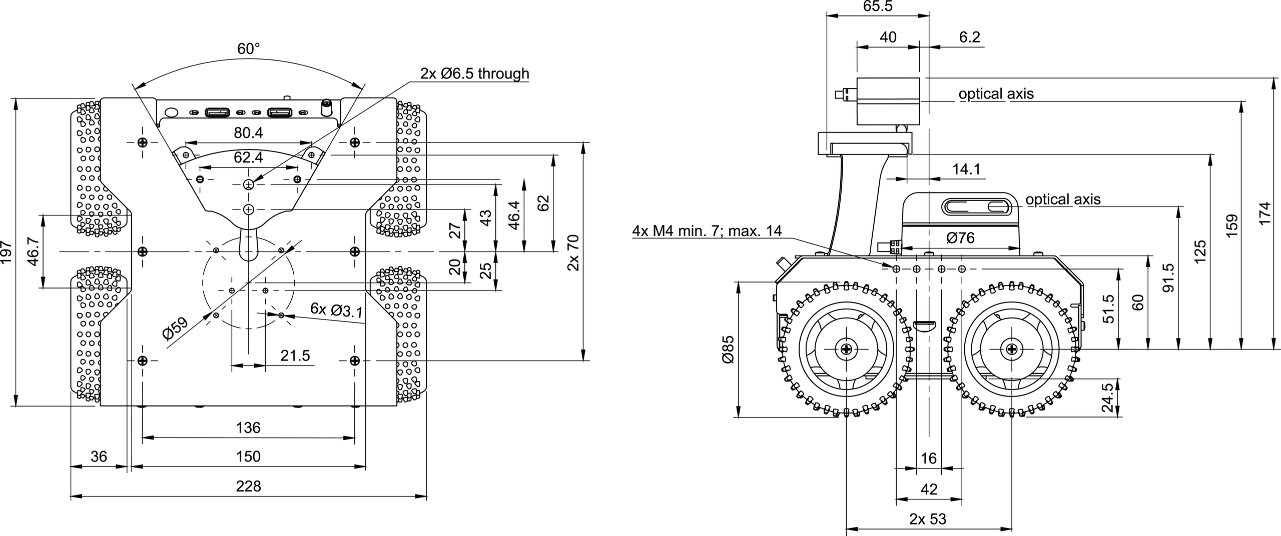
| Dimensions with camera and LiDAR | 198 x 228 x 218 mm / 7.80 x 8.98 x 8.58 in [L x W x H] |
| Dimensions without camera | 198 x 228 x 144 mm / 7.80 x 8.98 x 5.67 in [L x W x H] |
| Dimensions without camera and LiDAR | 198 x 228 x 103 mm / 7.80 x 8.98 x 4.06 in [L x W x H] |
| Weight | 2,84 kg / 100 oz (with camera and LiDAR), 2,45 kg / 86 oz (without camera and LiDAR) |
| Wheel diameter / Clearance / Wheelbase | 85 mm / 24 mm / 106 mm |
| Chassis material | Powder-coated aluminum plate, 1.5 mm thick |
| Maximum translational velocity | 1.0 m/s |
| Maximum rotational velocity | 420 deg/s (7.33 rad/s) |
| Maximum load capacity | Up to 5 kg / 176 oz *not in continuous work |
| Battery life | 1.5h - 5h |
Components
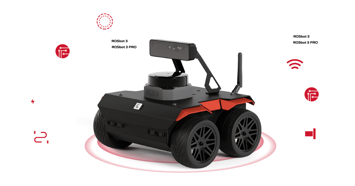
- ROSbot 3 / ROSbot 3 PRO
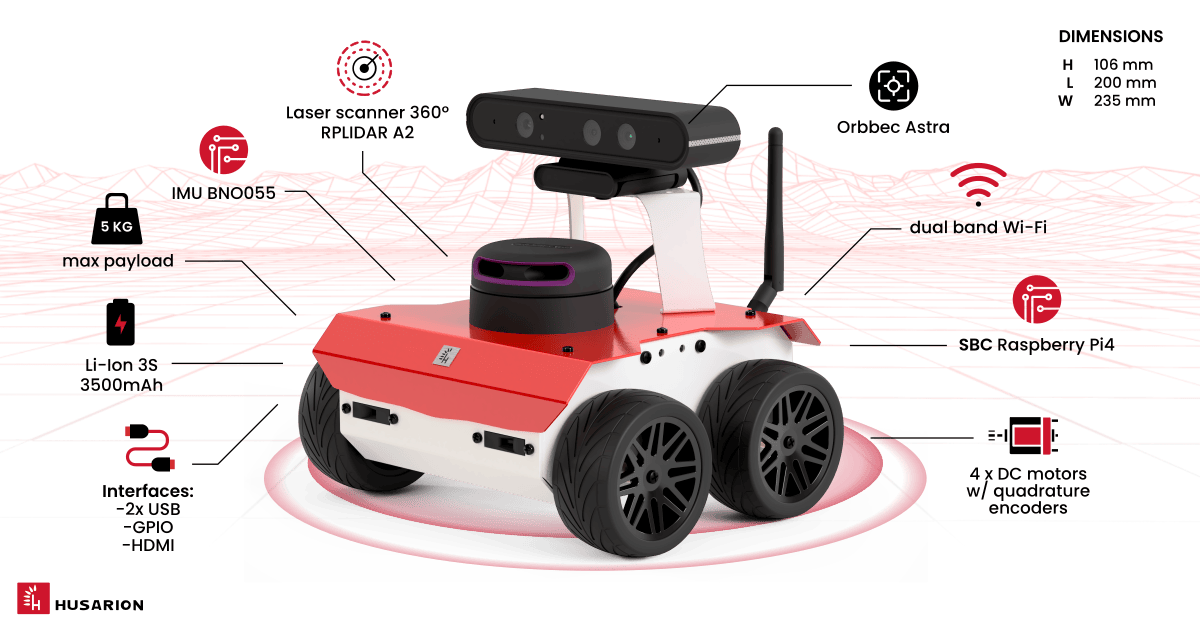
- ROSbot 2R
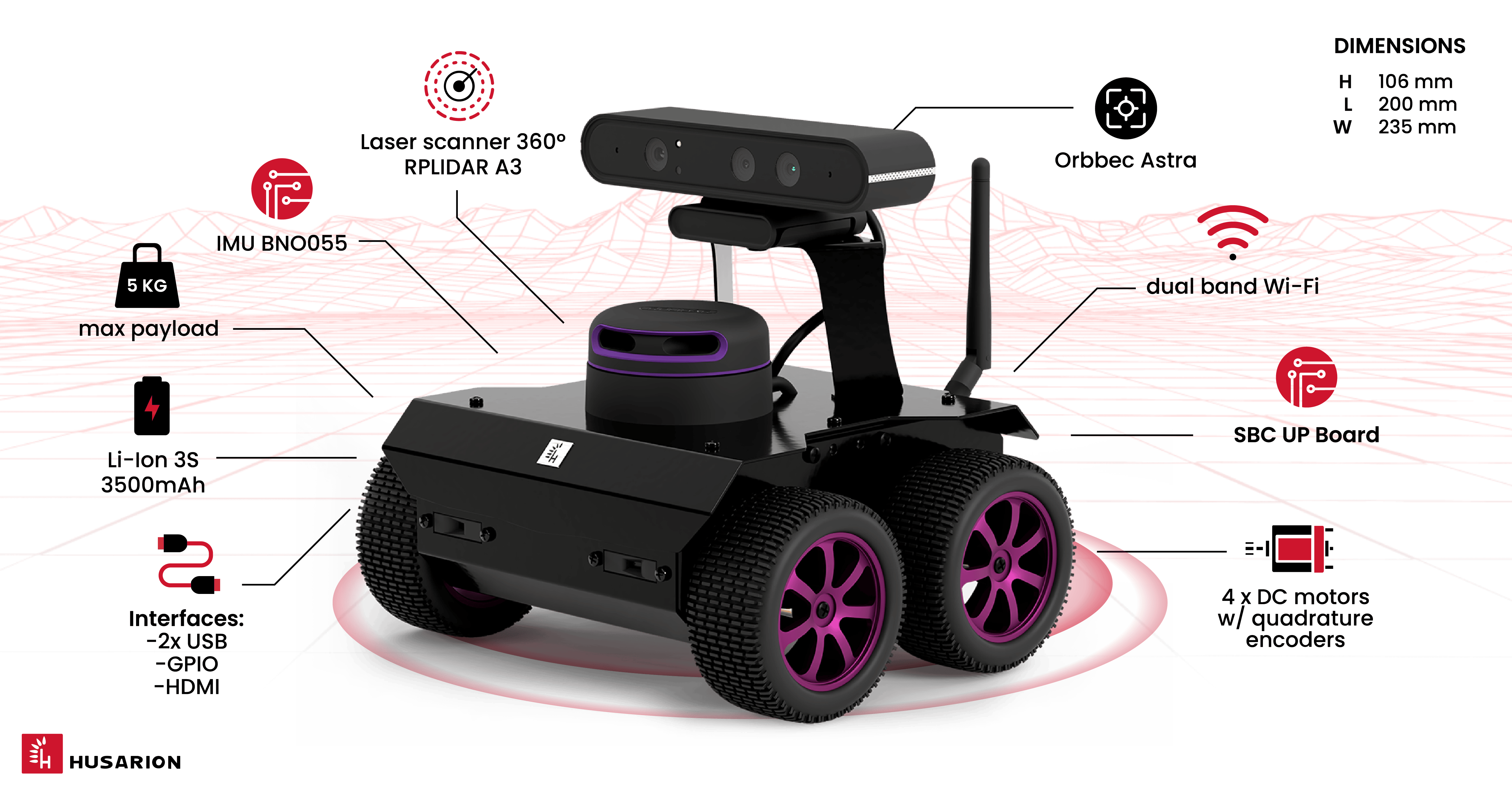
- ROSbot 2 PRO
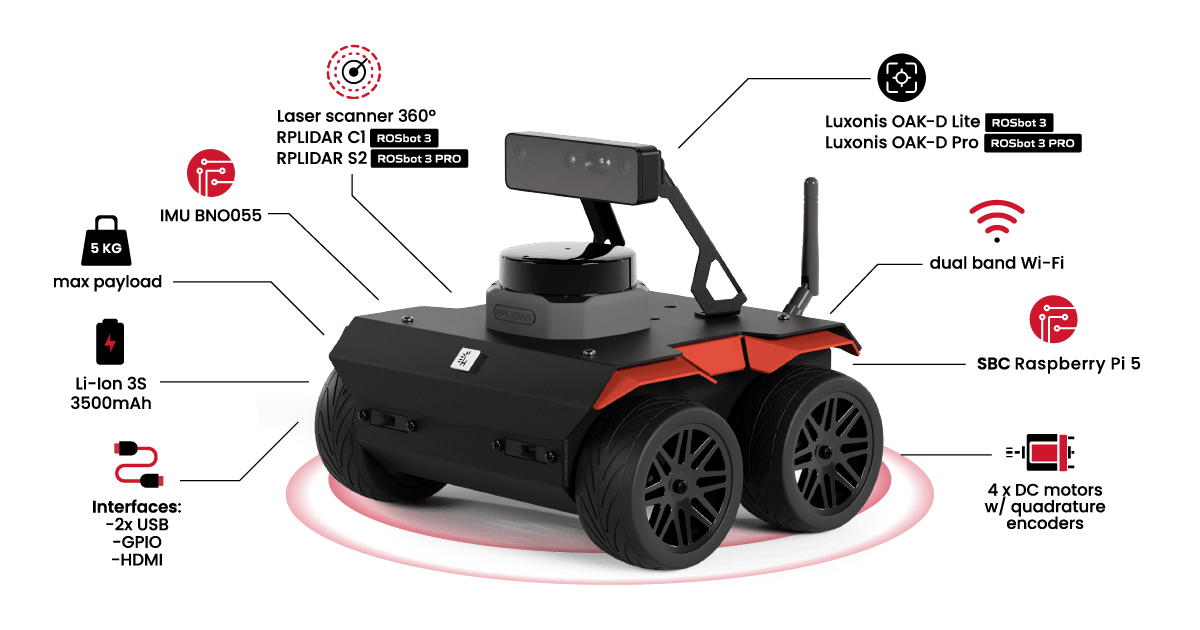
Components description
| Component | Quantity | Description |
|---|---|---|
| Infrared distance sensor | 4 | VL53L0X Time-of-Flight distance sensor with up to 200 cm range, more details |
| Built-in Microcontroller | 1 | STM32F407. |
| DC motor | 4 | Xinhe Motor XH-25D, Motor used: RF-370, 6VDC nominal, 6200rpm. Maximum mechanical power: 4W, no load speed at the output shaft: 180 rpm, stall torque at the output shaft: 2.9 kg*cm, stall current: 2.0A, gear ratio: ~34 (exact ratio is 30613/900) |
| Encoder | 4 | Magnetic, 48cpr, 12 poles |
| Batteries | 3 | Li-Ion 18650 protected, rechargeable batteries, 3500mAh capacity, 3.7V nominal voltage. Note: Device may be shipped interchangeably with similar batteries. |
- ROSbot 3 / ROSbot 3 PRO
- ROSbot 2R
- ROSbot 2 PRO
- ROSbot 2
| Component | Quantity | Description |
|---|---|---|
| SBC | 1 | Raspberry Pi 5 (ARM64 architecture) quad-core ARM-8 Cortex A76 @ 2.4GHz, 8GB RAM and 64 GB MicroSD flash memory. The SBC runs on Ubuntu-based OS, customized to use ROS. |
| 3D camera | 1 | Luxonis OAK-D Lite (in ROSbot 3) / OAK-D Pro (in ROSbot 3 PRO) |
| LIDAR | 1 | RPLIDAR C1 (in ROSbot 3) / S2 (in ROSbot 3 PRO), 360 degree, more details |
| IMU sensor | 1 | Intelligent 9-axis absolute orientation sensor BNO055, more details |
| Antenna | 1 | Dual-band, connected to the Wi-Fi USB adapter. |
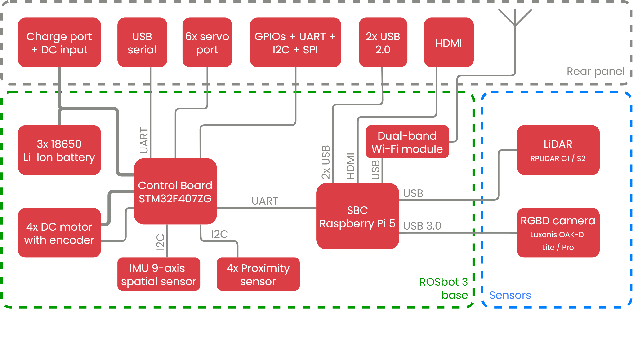
Block diagram
Graphic representation of ROSbot 3 components and connections between them.
| Component | Quantity | Description |
|---|---|---|
| SBC | 1 | Raspberry Pi 4 with Broadcom BCM2711 (ARM64 architecture) quad-core ARM-8 Cortex-A72 1.5 GHz, 4GB RAM and 32 GB MicroSD.. The SBC runs on Ubuntu-based OS, customized to use ROS. |
| 3D camera | 1 | Orbbec Astra with RGB image size 640x480 and depth image size 640x480. |
| LIDAR | 1 | RpLidar A2, 360 degree and up to 12m range, more details |
| IMU sensor | 1 | Intelligent 9-axis absolute orientation sensor BNO055, more details |
| Antenna | 1 | Dual-band, connected to the Wi-Fi USB adapter. |
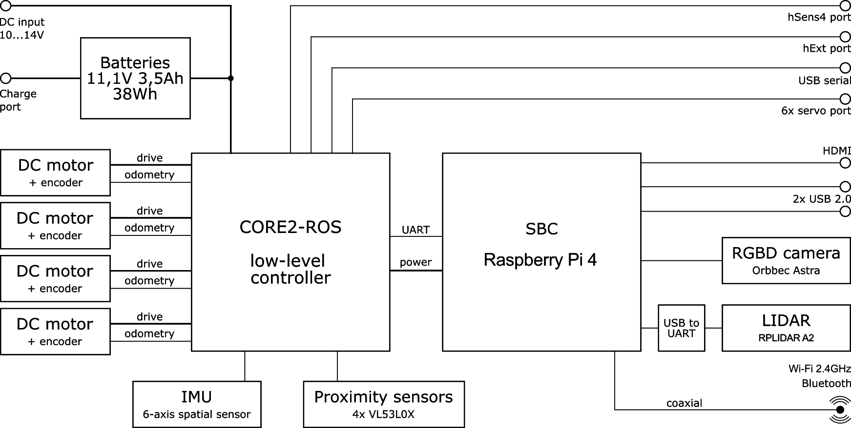
Block diagram
Graphic representation of ROSbot 2R components and connections between them.
| Component | Quantity | Description |
|---|---|---|
| SBC | 1 | UpBoard with 4 GB RAM, Quad-Core Intel Atom Z8350 1,92 GHz as CPU, a Intel® HD 400 Graphics as a GPU and 32GB eMMC. The SBC runs on Ubuntu-based OS, customized to use ROS. |
| 3D camera | 1 | Orbbec Astra with RGB image size 640x480 and depth image size 640x480. |
| LIDAR | 1 | RpLidar A3, 360 degree and up to 25m range, more details |
| IMU sensor | 1 | Powerful 9-Axis Accel/Gyro/Magnetometer sensor with MPU-9250, more details or Intelligent 9-axis absolute orientation sensor BNO055, more details |
| Antenna | 1 | 2.4GHz, connected to the Wi-Fi USB adapter with RP-SMA(f) ⟷ I-PEX MHF cable. |
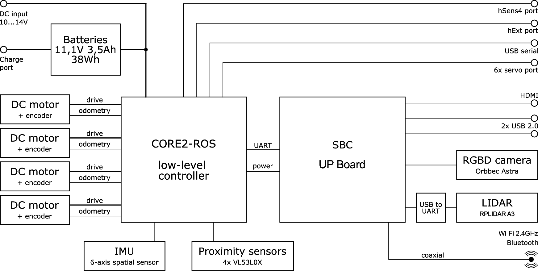
Block diagram
Graphic representation of ROSbot 2 PRO components and connections between them.
| Component | Quantity | Description |
|---|---|---|
| SBC | 1 | Asus Tinker Board with 2 GB RAM, Rockchip RK 3288 with 4x 1.80 GHz as CPU and a ARM Mali-T764 MP2 as a GPU and 32 GB MicroSD. The SBC runs on Ubuntu-based OS, customized to use ROS. |
| 3D camera | 1 | Orbbec Astra with RGB image size 640x480 and depth image size 640x480. |
| LIDAR | 1 | RpLidar A2, 360 degree and up to 8m range, more details |
| IMU sensor | 1 | Powerful 9-Axis Accel/Gyro/Magnetometer sensor with MPU-9250, more details or Intelligent 9-axis absolute orientation sensor BNO055, more details |
| Antenna | 1 | 2.4GHz, connected directly to the Asus Tinker Board Wi-Fi module. Uses an RP-SMA(m) ⟷ I-PEX MHF4 cable to connect the antenna with SBC. |
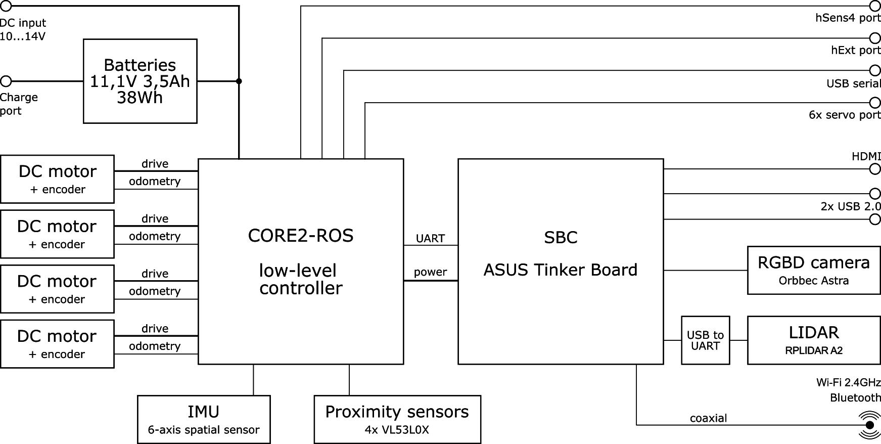
Block diagram
Graphic representation of ROSbot 2 components and connections between them.
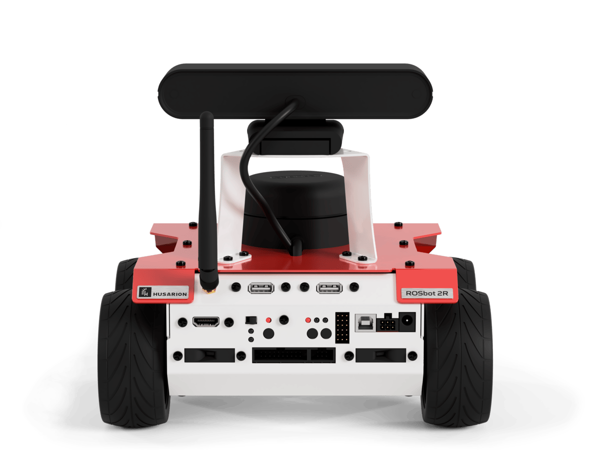
Rear panel description
- ROSbot 3 / ROSbot 3 PRO
- ROSbot 2R
- ROSbot 2 PRO
- ROSbot 2
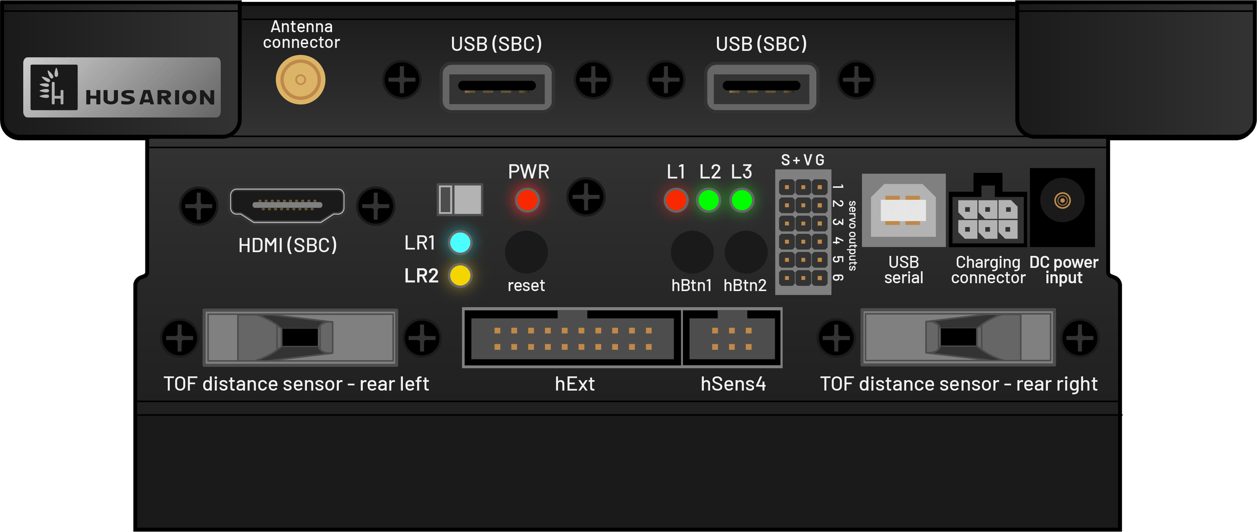
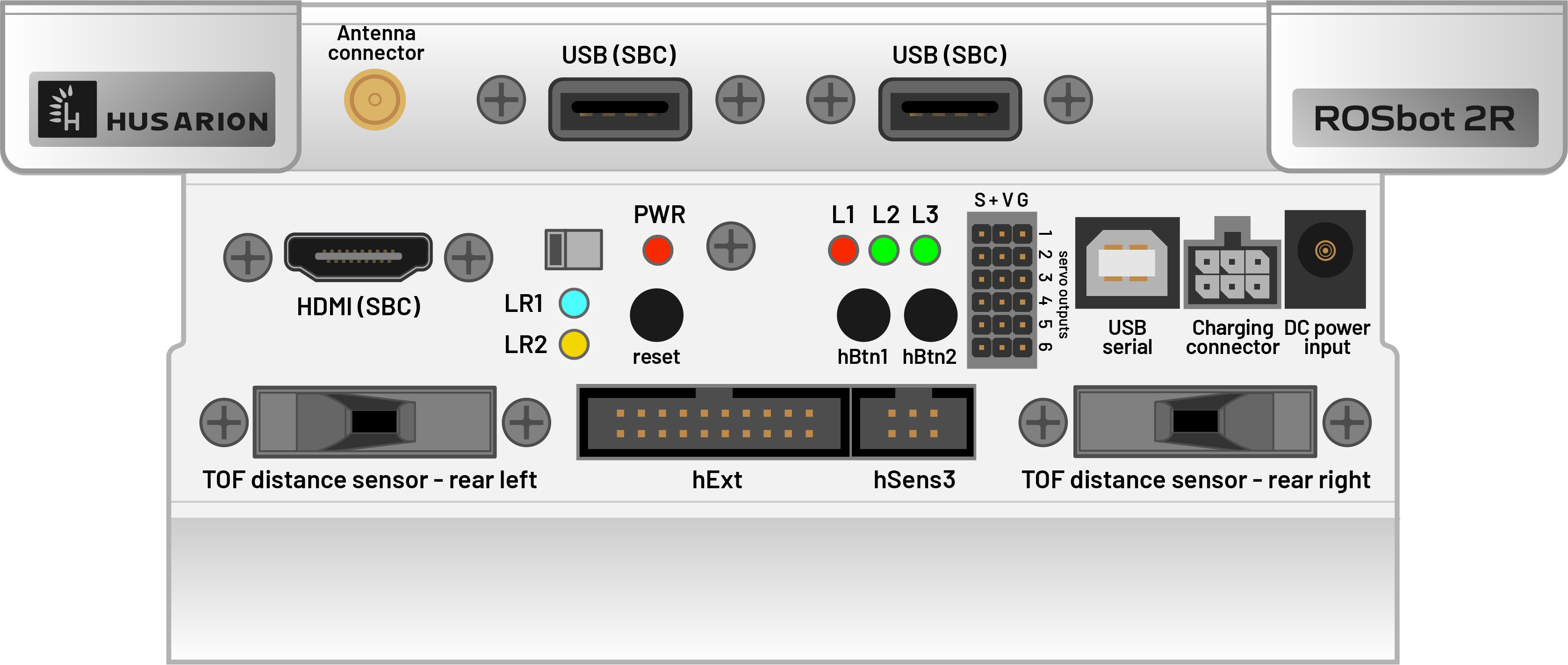
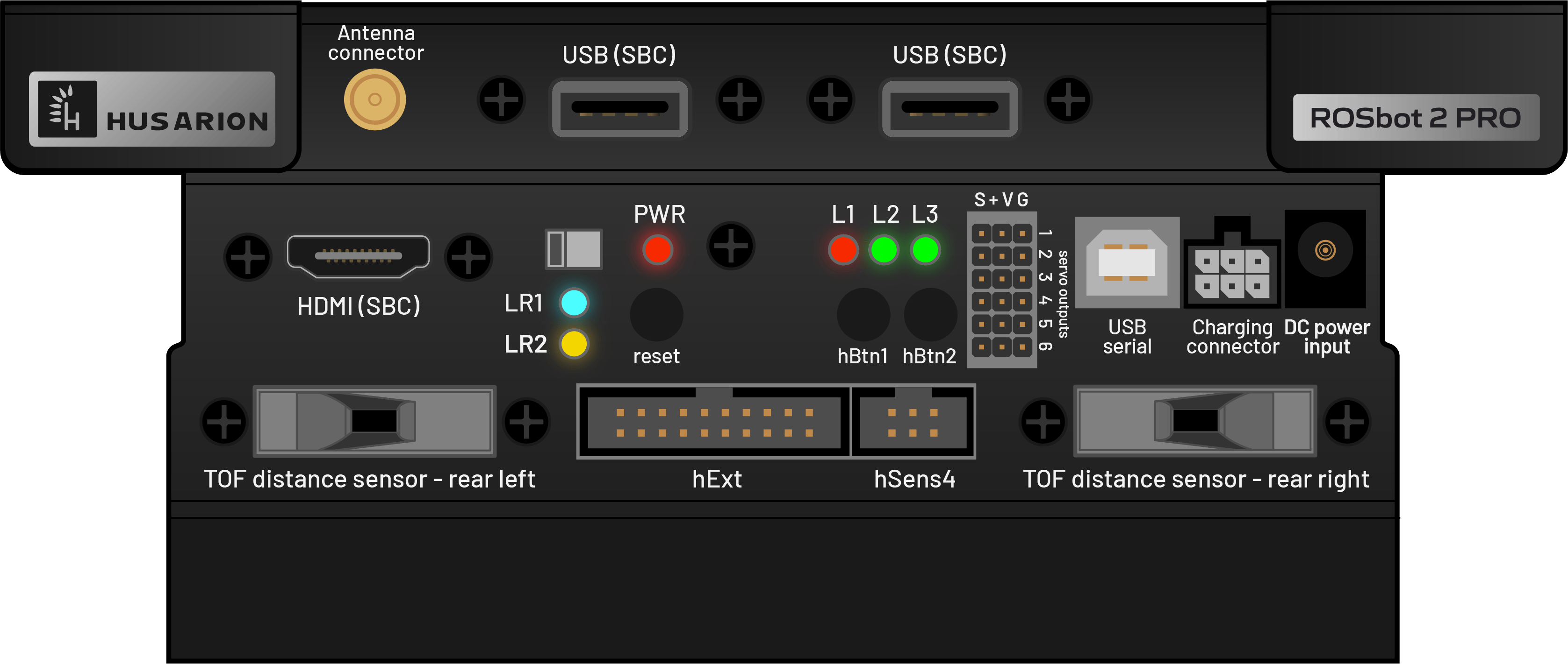
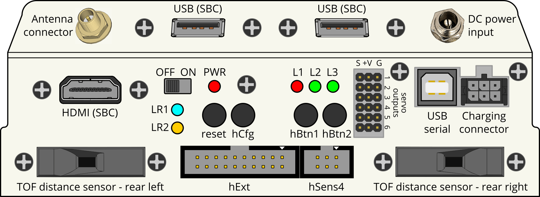
| Component | Quantity | Description |
|---|---|---|
| Antenna connector | 1 | Wi-Fi antenna RP-SMA socket - required for Wi-Fi connectivity |
| USB | 2 | USB 2.0 host ports from SBC |
| HDMI | 1 | HDMI output from SBC |
| Power switch | 1 | Turns ROSbot completely ON or OFF |
| LEDs | 6 | LR1(blue), LR2(yellow), L1(red), L2(green), L3(green), PWR(red). See LED statuses below. |
| Reset button | 1 | Button used for reset CORE2 |
| hBtn | 2 | hBtn1, hBtn2 - programmable buttons |
| Outputs for servo | 6 | Servo output with PWM, more details here |
| USB serial | 1 | USB serial port used for debugging the firmware on CORE2-ROS controller |
| Charging connector | 1 | 6-pin connector for charging internal Li-Ion batteries |
| DC power input | 1 | DC for working with external 12V power supply - use the power supply included with charger or any 12V, min. 5A power supply with 5.5/2.5mm plug (center-positive) |
| Time-of-Flight distance sensor | 2 | VL53L0X Time-of-Flight distance sensor with up to 200 cm range, more details here |
| hExt | 1 | 12xGPIO, 7x ADC, SPI, I2C, UART, more details here |
| hSens | 1 | 4 xGPIO, ADC, UART, more details here |
LED statuses
| LED | Role | Behavior |
|---|---|---|
| 🔵 LR1 | RPi status | On — problem with the RPi (robot's computer), hRP pin 3 |
| 🟡 LR2 | MCU status | On — MCU in bootloader (BOOT0), or STM32 not running correctly |
| 🔴 L1 | Firmware indicator | Off — everything OK Solid on — no communication with firmware / ROS driver not running Blinking — low battery (overrides the above) |
| 🟢 L2 | User | Programmable from ROS 2 (/leds topic) |
| 🟢 L3 | User | Programmable from ROS 2 (/leds topic) |
L1 is a status indicator driven by the firmware. L2 and L3 are user-programmable through the /leds topic (std_msgs/msg/UInt8), where each bit controls one LED: bit 0 (value 1) → L2, bit 1 (value 2) → L3.
# Turn L2 on
ros2 topic pub /leds std_msgs/msg/UInt8 "data: 1"

# Turn L2 and L3 on
ros2 topic pub /leds std_msgs/msg/UInt8 "data: 3"
Power supply
ROSbot is powered from an internal, rechargeable Li-Ion battery pack that contains 3 Li-Ion cells, connected in series. This type of connection is called “3S”. The schematic below explains how the cells are wired together and with the charging connector (on ROSbot side).
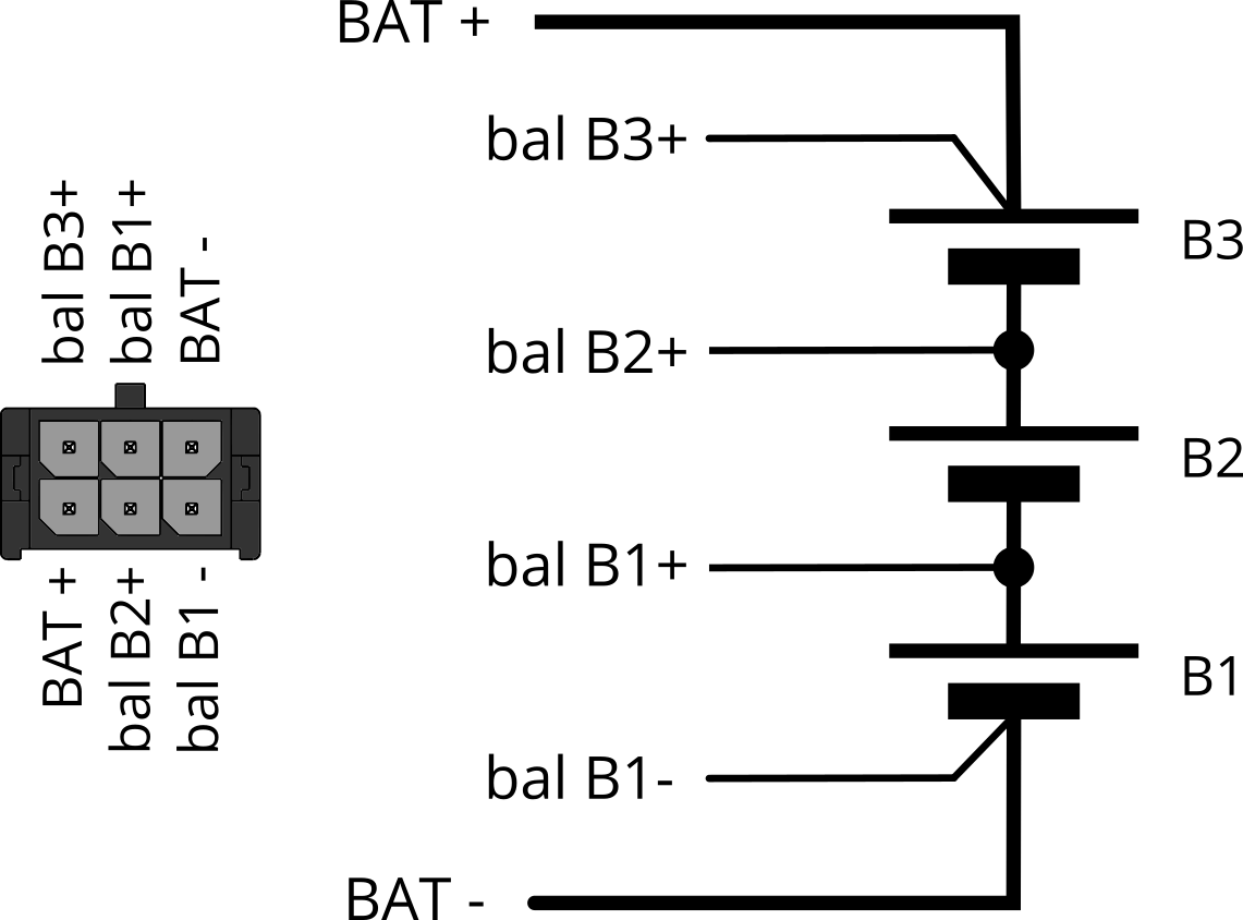
The BAT+ and BAT- are the power connections and the “bal Bxx” wires are used to monitor the voltage on each cell. It is strongly recommended to keep equal voltages on each cell during the charging process. The charger included with ROSbot can charge batteries in the described way and, thanks to that, the long life of the battery set is possible.
The nominal voltage of each cell is 3.7V but the useful range is 3.2V to 4.2V.
Important - discharge indicator If only the right firmware is preloaded to the internal controller (CORE2), the LED1 is programmed to indicate the power status:
- the LED1 is on when the robot is turned on
- the LED1 is blinking when battery is low – please charge immediately!
Please make sure that the user firmware always contains the function that monitors the supply voltage level. Deep discharging of batteries may decrease their lifecycle. Discharging to the voltage lower than 3.0V/cell can also trigger the over discharge protection. If the voltage is too low, turn ROSbot off and charge batteries as soon as possible.
Charging ROSbot
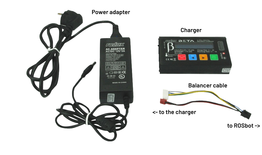
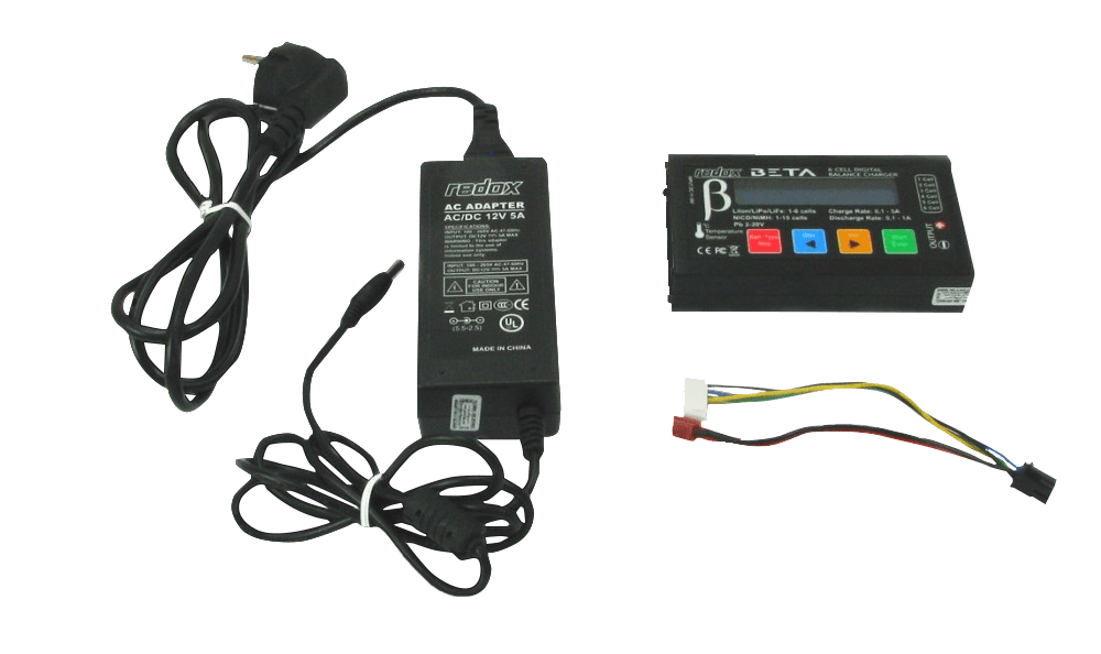
The ROSbot kit contains the Redox Beta charger. It is an universal charger, suitable for charging NiCd, NiMH, Li-Po, Li-Fe, Li-Ion and Pb (AGM, VRLA) batteries. ROSbot shall be charged using an included charger and cable.
Charger kit includes:
- Redox Beta charger
- AC/DC power adapter 100...240V to 12V 5A with 5.5/2.5mm plug on the 12V side
- a cable to connect charger with ROSbot charging port
Quick charging guide:
- Connect the power adapter to the charger and the output cable between charger and ROSbot (2 connectors on charger side, 1 black connector to ROSbot charging port).
- Use red and blue buttons to select “LiPo BATT” mode and press [Start].
- Use arrows to select “LiPo CHARGE” mode.
- Press [Start] - the current value should start blinking. Use arrows to set the current to 1.5A.
- Press [Start] again - the voltage value should start blinking. Select “11.1V(3S)” using arrows. The picture below shows the desired result.
- Press and hold [Start] for 2 seconds. The charger should now ask for confirmation. Press [Start] again. The charging process should begin now.
- When the charging will be finished (after about 3 hours), the charger will generate a loud “beep” sound and will finish charging at the same time.

If you need more information about charging, please read the Charging manual for ROSbot in PDF format.
Notes
- You can change charging current to maximum 3A. Please note that a regular charging with the maximum current can shorten the battery life.
- If you are going to use ROSbot stationary for a long time, you can use ROSbot with charger or power supply connected all the time. Please see the Charging manual for ROSbot for details.
- In case you need to replace batteries, use only 18650 Li-Ion batteries, with the capacity in a range of 1800...3500mAh and with a protection circuit! Using unprotected batteries may result in serious injuries or fire.
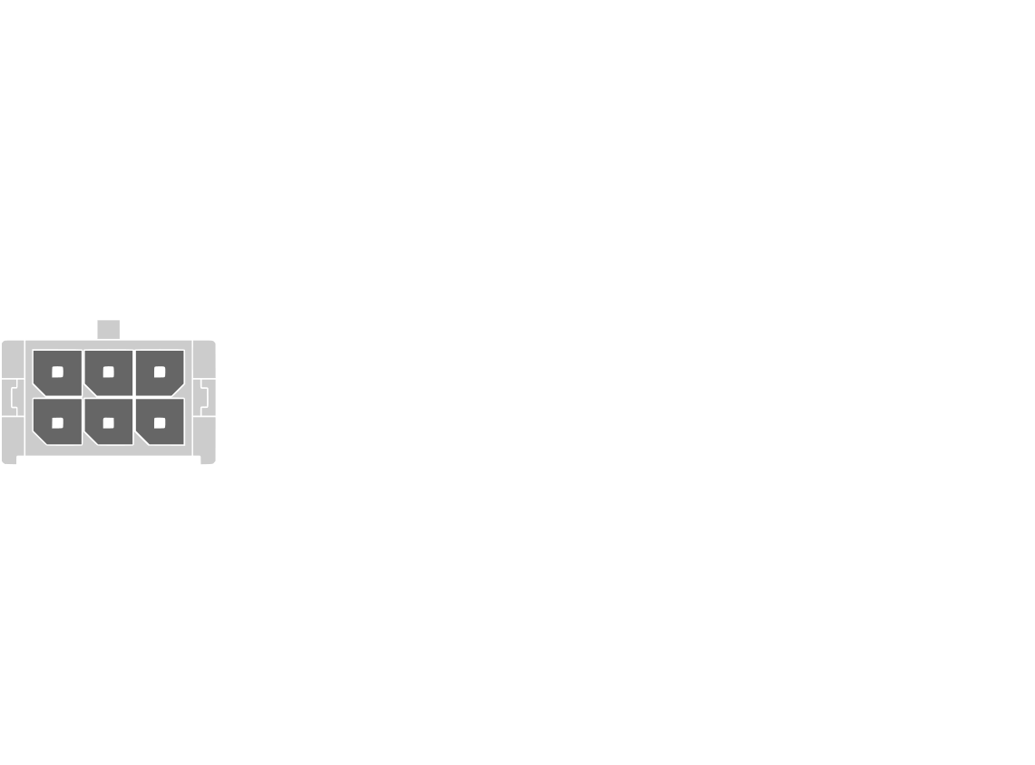
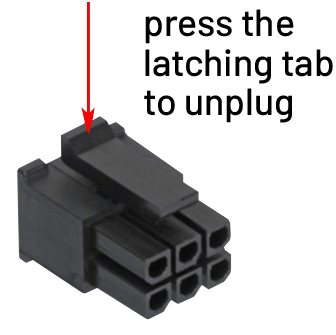
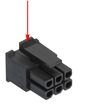
- Unplug charging connectors carefully. You shall not unplug the charger connectors holding the wires. The balancer connection on ROSbot side has a latching tab (see photo below) that must be pressed before unplugging. On the charger side there is no latching tab but you should also unplug this connector holding the white plug.
Software
Software for ROSbot can be divided into 2 parts:
- A low-level firmware that works on the real-time controller (CORE2). It can be developed using Visual Studio Code IDE.
- OS based on Ubuntu, which runs on the SBC (Raspberry Pi 4, UP Board, or Asus Tinker Board) and contains all components needed to start working with ROS or ROS 2 immediately. The microSD card or MMC memory with OS is included with each ROSbot. The OS has been modified to make the file system insensitive to sudden power cuts.
ROSbot 3 runs Husarion OS (Ubuntu 24.04 with ROS 2 Jazzy). The ROS 2 driver and the sensor drivers come as snaps, and the Husarion Cockpit web interface runs as a Docker Compose bundle. Older ROSbots use Docker containers.
The guides for the software running on ROSbot are in the Software section of the sidebar:
- Network: how the network is set up and how to change the Wi-Fi network from the terminal.
- ROS 2 API: topics, services and nodes of the ROSbot driver and firmware.
- Firmware installation: flashing the low-level firmware.
- Operating system reinstallation: restoring the default system image.
ROS / ROS 2 Tutorials
- ROS
- ROS 2
ROS (Robot Operating System) offers libraries and tools to help software developers create robotic applications. It provides hardware abstraction, device drivers, libraries, visualizers, message-passing, package management, and more. It's very powerful and functional tool dedicated to design robots. We created the set of ROS Tutorials dedicated for this platform to make it easier to familiarize yourself with these frameworks.
ROS 2 (Robot Operating System 2) provides libraries and tools to help software developers create robotic applications. We've put together a series of ROS 2 Tutorials dedicated for this platform that serve as a practical introduction to ROS 2. You can run them on any of our ROSbots, either on a physical robot or in the simulation environment. These step-by-step guides are tailored to accommodate both beginners embarking on their ROS 2 journey and experienced users looking to deepen their understanding of robot navigation.
Docs and links
All helpful documents and links in one place:
- ROSbot Safety Instructions - important!
- Husarion limited warranty terms and conditions
- Charging manual for ROSbot
- ROSbot block diagram
- ROS tutorials for ROSbot
- ROSbot wheel swap manual
- ROSbot 2 PRO on ROS webpage
- ROSbot 2 on ROS webpage
- URDF model of ROSbot - for Gazebo integrated with ROS
- ROSbot project on hackaday.io
- ROSbot project on instructables.com