CORE2
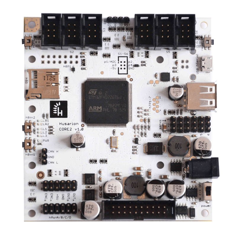
Electrical specification
| Interface | Description | Parameters |
|---|---|---|
| Power input | 6.8-16V | 70...3000mA current consumption, depends on external modules standard 5.5/2.1 mm DC plug (centre-positive) |
| I/O ports | 54 | 3.3V/5V tolerant GPIOs series resistance is 330Ω |
| ADC | up to 13 channels | 12-bit resolution |
| PWM | up to 10 channels: 6x 3.3V, 4x H-bridge output | Frequency range for H-bridge: 1Hz...21khz (in 16 steps) Period range for 3.3V outputs: 1...65535 us |
| UART | up to 4 channels | baudrate: 4800, 9600, 14400, 19200, 38400, 57600, 115200, 128000, 256000, 1000000, 2000000, 4000000 |
| I2C | 3 channels | up to 400kHz |
| SPI | 1 | up to 1 Mbps |
| CAN | 1 | 500kbps |
| External Interrupts | up to 8 channels | triggered by an edge or voltage level |
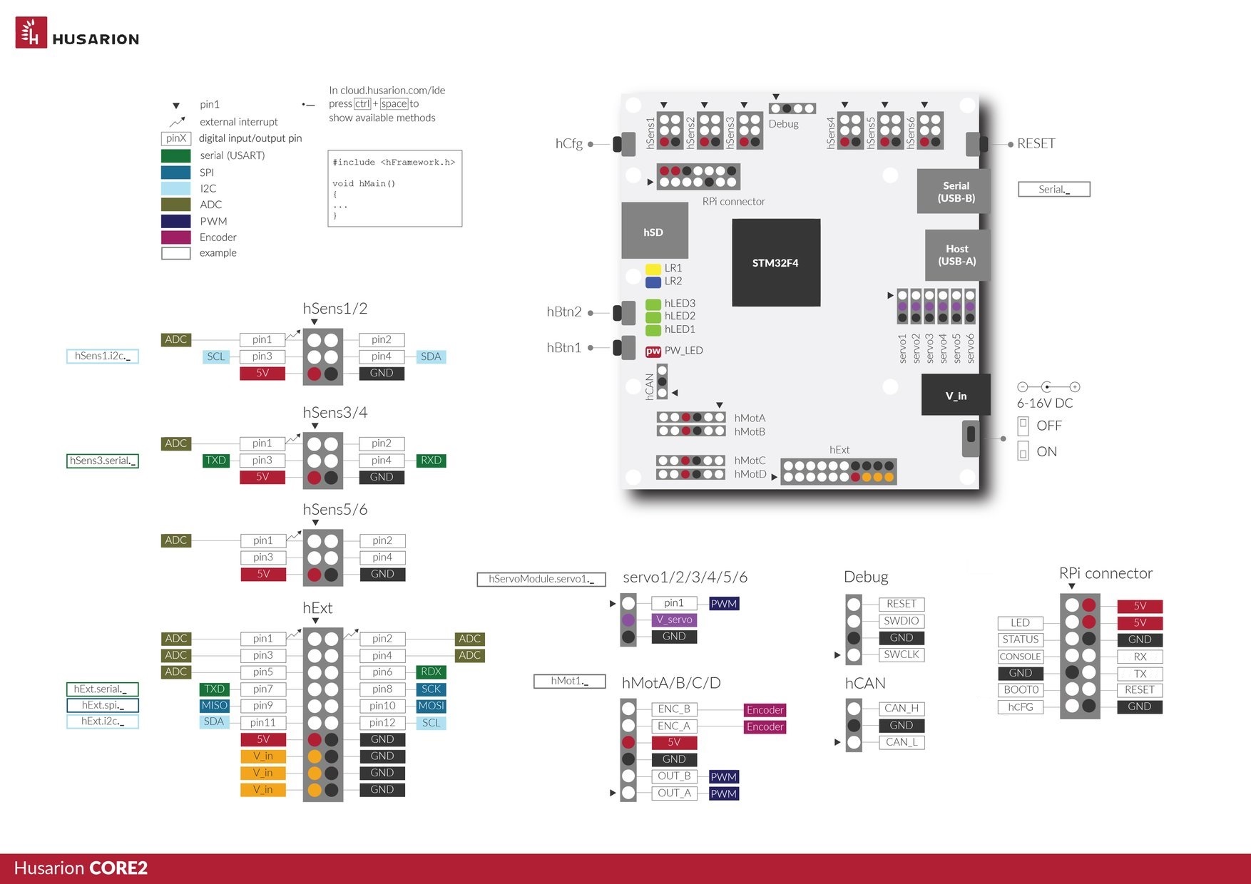
Ports description
hSensor
CORE2 is equipped with six hSensor ports (Shrouded Box Header: 2×3-Pin, 0.1" (2.54 mm) Male).
The hSensor is intended to be used with many different sensors, such as spatial orientation sensors (like MPU9250), light sensors, sound sensors, limit switches and many others.
This port is compatible with LEGO® MINDSTORMS® sets when a special adapter for CORE2 is used.
Each hSensor port contains three basic elements:
-
An Analog to Digital Converter (ADC) channel. The full range is 0 – 3.3V. The alternative function is interrupt input.
-
An auxiliary 5V supply output dedicated to supplying the sensor circuit. The maximum current is not limited for each port, but due to the 5 V line total current limit, we recommend keeping the current below 50mA. If you are sure that the total 5V current will not exceed 2A, you can go higher, up to 500mA. See "Power supply" section for more details.
-
4 digital inputs/outputs. Additionally, some hSensor ports have a hardware UART interface assigned to these IO’s, and some have a hardware I2C interface. If you want UART or I2C, please check the software documentation which physical ports to use.

| hSensor pin | Software name | Default function | Alternate function |
|---|---|---|---|
| 1 | hSensX.pin1 | GPIO | external interrupt input, ADC converter |
| 2 | hSensX.pin2 | GPIO | |
| 3 | hSensX.pin3 | GPIO | I2C_SCL (in hSens 1 & 2), UART_TX (in hSens 3 & 4), no alt. function (in hSens 5 & 6) |
| 4 | hSensX.pin4 | GPIO | I2C_SDA (in hSens 1 & 2), UART_RX (in hSens 3 & 4), no alt. function (in hSens 5 & 6) |
| 5 | - | +5V power supply output | |
| 6 | - | GND (0V) |
Advice: use ctrl + SPACE after typing "software_name." to see methods in the web IDE.
Using ADC
hSens1.pin1.enableADC();
while (true) {
	// read analog value (voltage 0.0 - 3.3V)
	float v_analog = hSens1.pin1.analogReadVoltage();

	// read raw value (voltage 0x0000 - 0x0fff)
	uint16_t v_int = hSens1.pin1.analogReadRaw();

	printf("%f | %d\r\n", v_analog, v_int);
	sys.delay(50);
hExt
CORE2 is equipped with one hExt port (Shrouded Box Header: 2×10-Pin, 0.1" (2.54 mm) Male).
hExt is a universal expansion port which contains 12 GPIO pins and very popular communication interfaces used in embedded systems: UART, I2C and SPI. The purpose of this port is to enable the communication with various electronic modules, (e.g. with the external servo driver) or creation your own ones.
Each hExt port contains:
- 12 x GPIO. Three of these can be configured as external interrupts, seven pins have an ADC converter as an alternative function and two can detect external interrupt contidtions.
- UART interface (can be used as two additional GPIOs).
- SPI interface (can be used as three additional GPIOs).
- I2C interface (can be used as two additional GPIOs).
- +5V supply voltage. Be aware that the 5V line is shared among all devices supplied with 5V. If you are sure that the total 5V current will not exceed 2A, you can go up to 500mA. See "Power supply" section for more details.
All interfaces are compatible with 3.3V CMOS logic. The A/D converter range is 0 - 3.3 V.

Pin functions
| hExt pin | Software name | Default function | Alternate function |
|---|---|---|---|
| 1 | hExt.pin1 | GPIO | external interrupt input, ADC converter |
| 2 | hExt.pin2 | GPIO | external interrupt input, ADC converter |
| 3 | hExt.pin3 | GPIO | ADC converter |
| 4 | hExt.pin4 | GPIO | ADC converter |
| 5 | hExt.pin5 | GPIO | ADC converter |
| 6 | hExt.serial.pinRx | UART RX | GPIO |
| 7 | hExt.serial.pinTx | UART TX | GPIO |
| 8 | hExt.spi.pinSck | SPI SCK | GPIO |
| 9 | hExt.spi.pinMiso | SPI MISO | GPIO, ADC converter |
| 10 | hExt.spi.pinMosi | SPI MOSI | GPIO,ADC converter |
| 11 | hExt.i2c.pinSda | I2C SDA | GPIO |
| 12 | hExt.i2c.pinScl | I2C SCL | GPIO |
| 13 | - | +5V power supply output | - |
| 14 | - | GND (0V) | - |
| 15 | - | +Vin (6-16V) power supply output | - |
| 16 | - | GND (0V) | - |
| 17 | - | +Vin (6-16V) power supply output | - |
| 18 | - | GND (0V) | - |
| 19 | - | +Vin (6-16V) power supply output | - |
| 20 | - | GND (0V) | - |
Communication interfaces
| hExt communication interface | Software name | Parameters |
|---|---|---|
| USART | hExt.serial | baudrate: 4800, 9600, 14400, 19200, 38400, 57600, 115200, 128000, 256000, 1000000, 2000000, 4000000 |
| SPI | hExt.spi | up to 1 Mbps |
| I2C | hExt.i2c | up to 400kHz |
hServo
You can connect up to 6 servo motors directly to CORE2. Power supply is onboard thanks to integrated DC/DC converter with selectable voltage output (remember that there is one power supply voltage for all servos).

| hServo pin | Description | Parameters |
|---|---|---|
| 1 | PWM output | 3.3V standard, pulse width: 1 - 65535 us, pulse period: 1 - 65535 us (can not be higher than pulse width) |
| 2 | Servo power supply output | selectable voltage level: 5V / 6V / 7.4V / 8.6V (tolerance +/- 0.2V), maximum current comsuption for all servos: 2.5A (continuous) , 4A (peak) |
| 3 | GND (0V) | up to 400kHz |
hServoModule.enablePower();
hServoModule.s1.setPeriod(20000); //PWM period 20ms
while (1) {
	hServoModule.s1.setWidth(1000); //set pulse width: 1000us
	sys.delay(1000);
	hServoModule.s1.setWidth(2000);
	sys.delay(1000);
}
hMotor
CORE2 is equipped with four hMotor ports.
The hMotor is intended to be used with a DC motor with encoder, but you don’t have to use the encoder interface if you have a standard DC motor. The hMotor interface is fully-compatible with LEGO® MINDSTORMS® sets (remember that you have to use special adapter to use these sets).
Each hMot port contains three basic elements:
An H - bridge for driving the DC motor (with or without encoder) or a stepper motor. It can also be used for driving other devices, but don’t forget about a PWM signal on the output and its limitations. The maximum average output current for each hMot is 1A, and the maximum peak current is 2A. The H-bridge is supplied from the CORE2 power supply voltage Vin (6 - 16V) and you can expect the same at the H-bridge output.
An auxiliary 5V supply output dedicated to supplying the encoder circuit. The maximum current is not limited for each port, but due to the 5 V line total current limit, it is recommended keeping the current below 50mA. If you are sure that the total 5 V current will not exceed 2A, you can go higher, up to 1A. See "Power supply" section for more details.
A quadrature encoder interface is used to control position or speed of the electric motor shaft, so you know whether your control algorithm works as you expected. Husarion CORE2 uses hardware quadrature encoder interface provided by STM32F4 microcontroller (functionality built into some timer peripheral interfaces of STM32F4). For this reason you don't waste processing power of CPU to detect each slope on encoder output signal. Everything is done by special hardware interface, so you don't have to worry about missing any change of your motor shaft. Wikipedia provides an accessible explanation how encoders work: incremental rotary encoder.
The encoder interface is compatible with the majority of popular optical and magnetic encoders integrated with motors or sold separately.

| hMot pin | Default function | Description |
|---|---|---|
| 1 | Output A | Output voltage: 0 - Vin (6-16V), Output current: 1A (continuous), 2A (peak) with built-in overcurrent protection |
| 2 | Output B | Output voltage: 0 - Vin (6-16V), Output current: 1A (continuous), 2A (peak) with built-in overcurrent protection |
| 3 | GND | Ground terminal |
| 4 | +5V output | Voltage supply for encoder circuit. Keep the maximum current below 50mA for each hMot port. |
| 5 | Encoder input A | 5V standard digital input for encoder interface (channel A) |
| 6 | Encoder input B | 5V standard digital input for encoder interface (channel B) |
Supported motor types
DC motor with encoder
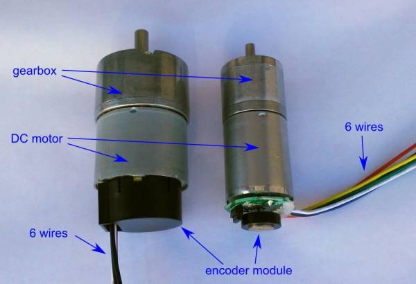
This motor type is suitable for more professional applications. It can be identified by 6 wires coming out of the encoder board. DC motor with quadrature encoder interface allows you to create own sophisticated control algorithm optimized for your application in contrast to RC servos that can't give any feedback to your algorithms.
Remember not to power your motors using higher voltage than recommended in their specification.
DC motor without encoder
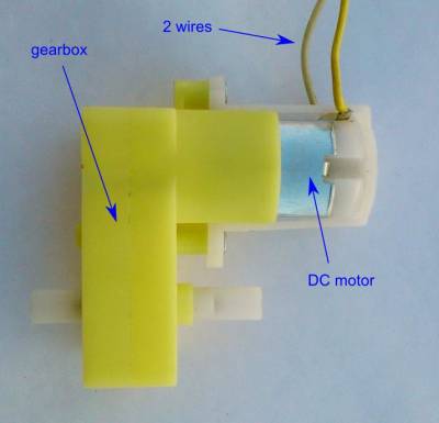
Of course, in many cases you don't need the encoder - e.g. if you need to drive wheels without sensing their position. In that case you can use a simple DC motor with gearbox. It can be identified by 2 wires coming out of the motor.
Despite the lack of the encoder, you still can recognize the extreme positions of your mechanism using the limit switches.
LEGO® motor
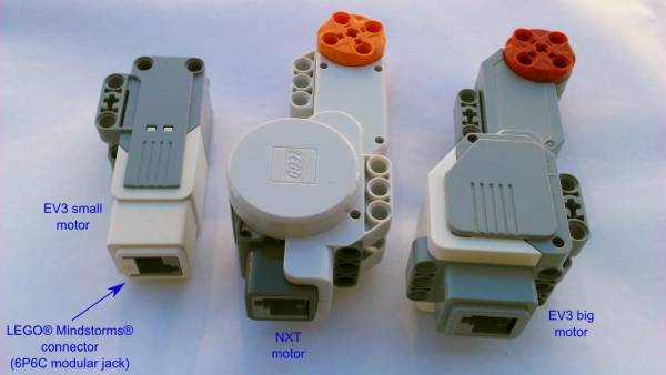
CORE2 is fully compatible with servomotors from LEGO® Mindstorms® when used with connector adapter. There are 3 types of LEGO® servomotors: motor from NXT/NXT2.0 kit and two types from EV3 kit. In fact, they are all motors with quadrature encoder. \ Remember that LEGO® motors have 9V nominal voltage and when you supply CORE2 with higher voltage, you should limit the PWM duty cycle.
Stepper motor
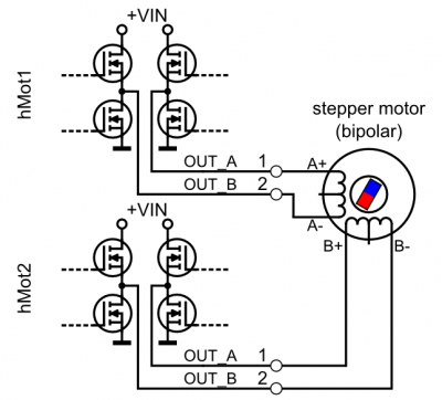
Connecting a bipolar stepper motor is also possible. In this case, you need two hMotor ports to drive one stepper motor. If your motor windings have 4 or 6 terminals, it can work in the bipolar configuration (the 6-terminal motors can work in both unipolar and bipolar configuration). In the picture you can see how to connect the bipolar motor with two H-bridge outputs.
hCAN
Basics
The CAN (Controller Area Network) is the best way to expand your device with more than one CORE2 or with other modules with a CAN interface. When two or more COREs are connected with hCAN they are able to send commands via a real-time network. One CORE2 is not enough for your application? No problem! Use as many CORE2's as you need for your projects and connect one of them to the Internet - every command will be executed very quickly. One CORE2 can be connected to the Internet while the others take care of all the sensors and motors.
Physical interface
For those who don’t know what CAN is, it’s a two-wire, bidirectional, differential bus, commonly used in automotive applications. You will find more on Wikipedia: CAN bus
We used a non-standard connector. The industrial standard is a 9-pin DSUB connector, but of course it's too large, so we decided to use a 3 pin, 2.54mm pitch header which.
Termination
Communication via CAN requires terminated transmission line. Thus, CORE2 has the selectable terminator on board. For short distances, terminator can be connected only to the one end of the bus. CORE2 has an optional jumper (to be soldered) that connects a 100Ω, 220Ω or both resistors to the line. Two CORE2s with two terminators (jumper soldered in 100Ω configuration) can communicate with full speed at long distances.
If you need to connect more than two CORE2s, you can attach jumpers in only one or two CORE2s and remove jumpers from the others to keep the total impedance greater than 45Ω. The special case is the "star" connection, where you can leave the termination only in one CORE2 that is the star common junction node. The recommended termination for this case is 100Ω or 100Ω||220Ω (in parallel) that gives the resistance ~69Ω.

| hCan pin | Signal | Description |
|---|---|---|
| 1 | CAN H | CAN high (positive) line |
| 2 | GND | Ground (0V) |
| 3 | CAN L | CAN low (negative) line |
DBG

If you are an advanced code developer you will probably appreciate it! The DBG connector allows you not only to upload the code to the CORE2, but it is also a debugging interface for the STM32F4 microcontroller.
To use the DBG interface, you need an additional hardware programmer/debugger: ST-LINK/V2. You can find the original one here: ST-LINK/V2
You also need to configure the offline development environment. You will find the instructions here: Husarion SDK
hSerial
The hSerial port is an USB device port with a standard micro B USB connector, but it's called "hSerial" because this port is connected to the serial port of the microcontroller. It is not the native USB port - it uses the FTDI® chip to connect the internal serial port to your computer or other USB host.
The hSerial port can be used to:
- read logs from the CORE2 device on your computer,
- upload new software to the CORE2 microcontroller (if the wireless connection is not available),
- other communication with any USB host device (FTDI driver is needed).
CORE2 cannot be powered via the USB hSerial port!
USB host
The USB host connector has two functions:
- a full-speed, native USB 2.0 host port, that works with STM32F4 microcontroller (default),
- an expansion of the USB port from Raspberry Pi Zero (for more advanced users).
Independently from chosen function, it also works as a port for charging mobile devices. Data connection and charging (up to 1A) can be provided simultaneously.

The function is chosen by soldering small jumpers on the bottom side of the PCB (see the picture).
In the first case, the USB host port allows you to connect any smartphone or tablet with a USB device port or USB OTG port. If you are more familiar with programming, you can connect any compatible USB device. If you are a beginner, use the device supported by our libraries.
The second function of this port is provided for more advanced users, because it needs soldering the twisted-pair wire from Raspberry Pi Zero board to the CORE2 board. Thanks to that function, you are able to connect e.g. Wi-Fi dongle to the Raspberry Pi Zero without using the additional USB-OTG adapter.
The table below explains the jumpers functions.
| Position | Jumper 1 | Jumper 2 | Jumper 3 |
|---|---|---|---|
| A | USB works with STM32F4 | USB works with STM32F4 | USB power is controlled by STM32F4 |
| B | USB works with Raspberry Pi Zero | USB works with Raspberry Pi Zero | USB power is permanently switched on |
The second table explains in easy way which configuration is for you:
| USB function | Jumper 1 pos. | Jumper 2 pos. | Jumper 3 pos. |
|---|---|---|---|
| USB works with STM32F4 | A | A | A |
| USB works with Raspberry Pi Zero | B | B | B |
| Charging only (with no communication) | unsoldered | unsoldered | B |
| Charging controlled by STM32F4 (default) | unsoldered | unsoldered | A |
hSD
Just a connector for a standard microSD card. It uses one of the SPI interfaces available in the microcontroller. The rest is software.
LEDs and buttons

There are 3 green LEDs and 2 buttons to be controlled by user on CORE2. The hLED1, hLED2 and hLED3 are described as L1, L2, L3 on the PCB. The buttons hBtn1 and hBtn2 are placed near the LEDs.
The PWR LED is indicating that CORE2 board is powered and switched on.
The LR1, LR2 LEDs are used by modules connected to RPI connector.
LED1.off(); // initially off
LED2.on(); // LED2 will stay on
while (true) {
	LED1.toggle(); // toggle LED1
	sys.delay(500); // wait for 500 ms
}
In case you observe LEDs blinking in a strange way, it means that the microcontroller fell into hard fault state and needs reset. It can happen if you accidentally execute an inappropriate program code. The picture below shows how it looks like:
The buttons can be used in a very simple way:
while (true) {
	if(hBtn1.isPressed() == 1){
		LED3.on();
	}else{
		LED3.off();
	sys.delay(50);
}
Power supply
Before powering the CORE2 you should know something about its power supply input.
The CORE2 input voltage (Vin) must be in the range 6 - 16V. The recommended input voltage range is 7 - 15V. The power connector is a standard DC 5.5/2.1 (centre-positive) type. The minimum power supply output current to run CORE2 itself is about 150mA@12V and 200mA@9V.
The CORE2-ROS input voltage (Vin) must be in the range 6.5 - 16V. The recommended input voltage range is 7.5 - 15V. The minimum power supply output current to run CORE2-ROS depends on SBC board used with CORE2. For Raspberry Pi, the minimum output current that must be provided from supply is about 1.5A@12V and 2A@9V. For ASUS Tinker Board the minimum current is 2A@12V and 2.7A@9V.
When using motors or other high-power modules with CORE2/CORE2-ROS, the minimum recommended power supply is 12V 5A or even more.
The CORE2 power supply input has overvoltage (>16V), reverse-polarity and overcurrent (~4A) protections. The long-term overvoltage state shall be avoided!
Block diagram

| Voltage line name | I max | Available on port: | Info |
|---|---|---|---|
| Vin | - | - | main power input |
| Vin(p) | 2A | hExt | gated main input |
| +5V | 2A | hMot, hRPI, USB host | |
| +5V(sw) | 1A | hSensor, hExt | drawn from +5V, switched by software |
| +3.3V | 0.5A | - | only for internal circuits |
| Vservo | 3A | hServoModule | programmable voltage: 5/6/7.4/8.2V |
Controlling servo power supply
hServoModule.enablePower(); //turn servo DC/DC power converter on
hServoModule.setPowerMedium(); //set 6V on DC/DC power converter output
How to power CORE2?
You can supply the CORE2 with:
- 5 - 10 AA/AAA cells;
- 6 - 11 NiCd/NiMH cells;
- 2 or 3 Li-Ion/Li-Poly cells (e.g. 18650 batteries);
- an AC-to-DC wall adapter;
- a 12 V lead-acid battery.
CORE2 cannot be supplied from the USB port of your laptop. Why? This is a controller designed for automation & robotics applications and has motor drivers on its board. Motors cannot be supplied from USB due to the current and voltage requirements. To avoid the risk of damaging the USB port we decided to supply CORE2 separately. CORE2 is designed to be programmed wirelessly and the USB connection is not the basic way to program or supply the controller (however, programming is possible through hSerial).
How much current does it need? It strongly depends on the robot configuration. A CORE2 without any devices connected needs up to 80mA. When you connect certain motors, current peaks can reach several amperes. The average current should not exceed 4A, otherwise the overcurrent protection will be triggered and unexpected resets will occur. Remember this when you are designing your device.
CORE2 has two internal voltage regulators. The input voltage (behind protection circuit) Vin(p) is converted to 5V by a switching regulator, and then to 3.3V by a linear voltage regulator. Be aware of the current limits – the total current must not exceed 2A through the 5V line. We will also remind you about power limitations in the description of individual interfaces.
The supply voltage +5V(sw) for hExt and hSens connectors can be switched on and off. It is enabled by default but can be switched off in the software.
Power supply alternatives
If you are not willing to use AA or similar alkaline batteries, the first alternative is to use NiCd or NiMH rechargeable batteries - but they have much lower nominal voltage. The better alternative are Li-Ion or Li-Poly batteries. Fortunately, these are available in the same shape as AA batteries and they are called “14500”. The name comes from their dimensions: 14x50mm.
Of course, you will also need a charger.
Remebmer that Li-Ion and Li-Poly batteries have higher nominal voltage and you have to use 3 cells instead of 6 cells. To do that, you can:
- use only one 3*AA battery holder with 3 Li-Ion/Poly batteries,
- use 6*AA battery holder with 3 “dummy” batteries and 3 Li-Ion/Poly batteries.
Internet access
To use CORE2 hardware from the cloud, you need to provide the Internet connection for CORE2.
This can be done thanks to cheap Wi-Fi module, such as ESP32 which is sufficient in most cases. In certain uses more computing power and andvanced onboard libraries (e.g. ROS - Robotic Operating System) are necessary CORE2 can be connected with a Linux computer (e.g. RaspberryPi). When working with Linux, cloud connection is not available, it can be flashed with offline tools like MBED framework.
Connecting CORE2 to the cloud
Use hConfig app (to be found on AppStore or Google Play) where wizard will guide you through all the steps required to connect your CORE2 to the Husarion cloud.
Status LEDs
There are 2 status LEDs - LR1 and LR2 - controlled directly from the ESP32/RPi device. These LEDs can't be controlled from STM32 microcontroller. The following table shows their behavior under different conditions:
| Mode | LR1 (yellow) | LR2 (blue) | Period | Behavior |
|---|---|---|---|---|
| Config mode | blinking alternately | 600 ms | ||
| Connecting | OFF | blinking | 300 ms | |
| Connected | OFF | ON | - | |
| Not configured | blinking | OFF | 100/1000 ms | |
| Invalid auth. | blinking | OFF | 100 ms | |
| No Internet | blinking | ON | 100 ms |
hRPI connector

Although the connector's name comes from Raspberry Pi, it is designed to be used with both ESP and Raspberry. CORE2 comes without any connector soldered because the connector type depends on module for Internet connection you are going to use in your project.
| hRPI pin | Signal name | Description |
|---|---|---|
| 1 | - | Not connected |
| 2 | +5V | Supply voltage (max. 1A) |
| 3 | LR2 | LED LR2 (cathode) |
| 4 | +5V | Supply voltage (max. 1A) |
| 5 | GPIO | GPIO (STM34F4) |
| 6 | GND | Ground (0V) |
| 7 | GPIO | GPIO (STM34F4) |
| 8 | UART RX | UART RX (STM32F4) |
| 9 | GND | Ground (0V) |
| 10 | UART TX | UART TX (STM32F4) |
| 11 | LR1 / BOOT0 | LED LR1 (anode) / BOOT0 pin (STM32F4) |
| 12 | RST | RST active-high (STM32F4) |
| 13 | hCFG | hCFG button |
| 14 | GND | Ground (0V) |
Updating firmware
In this section you will find instructions on how to update CORE2 bootloader when a newer version is available. You can also find information on how to install the newest image for external modules, that provide Internet access for CORE2.
Updating CORE2 bootloader
You need to have Visual Studio Code installed with Husarion extension. Please follow this guide if you haven't done this before: VSCode installation
- Locate core2-flasher utility (YOUR_HOME_PATH/.vscode/extensions/husarion.husarion-VERSION/sdk/tools/YOUR_ARCH/core2-flasher).
- Download the bootloader HEX file to the folder with core2-flasher
- Connect CORE2 to PC via USB.
- Install drivers (Windows only)
- Download Zadig Usb driver installer - Zadig
- Run Zadig
- Select FT231X USB UART in Zadig window
- Choose WinUSB driver and click Replace Driver
- Open command line prompt.
- Flash bootloader with commands:
on Linux in the terminal:
./core2-flasher --unprotect
./core2-flasher bootloader_1_0_0_core2.hex
./core2-flasher --protect
on Windows in the terminal:
core2-flasher.exe --unprotect
core2-flasher.exe bootloader_1_0_0_core2.hex
core2-flasher.exe --protect
OS image for RaspberryPi/Tinkerboard
Installing new image
- Download image for Raspberry Pi/Tinkerboard from here.
- Follow the official guide on raspberrypi.org webpage for writing image to SD card.
Updating OS
- Login to your CORE2-ROS.
- Execute in terminal:
apt-get update; apt-get dist-upgrade -y
Docs for download
All downloadable documents in one place:
- CORE2 Safety Instructions - important!
- CORE2 board mechanical drawing