ROSbot XL Manual
Overview
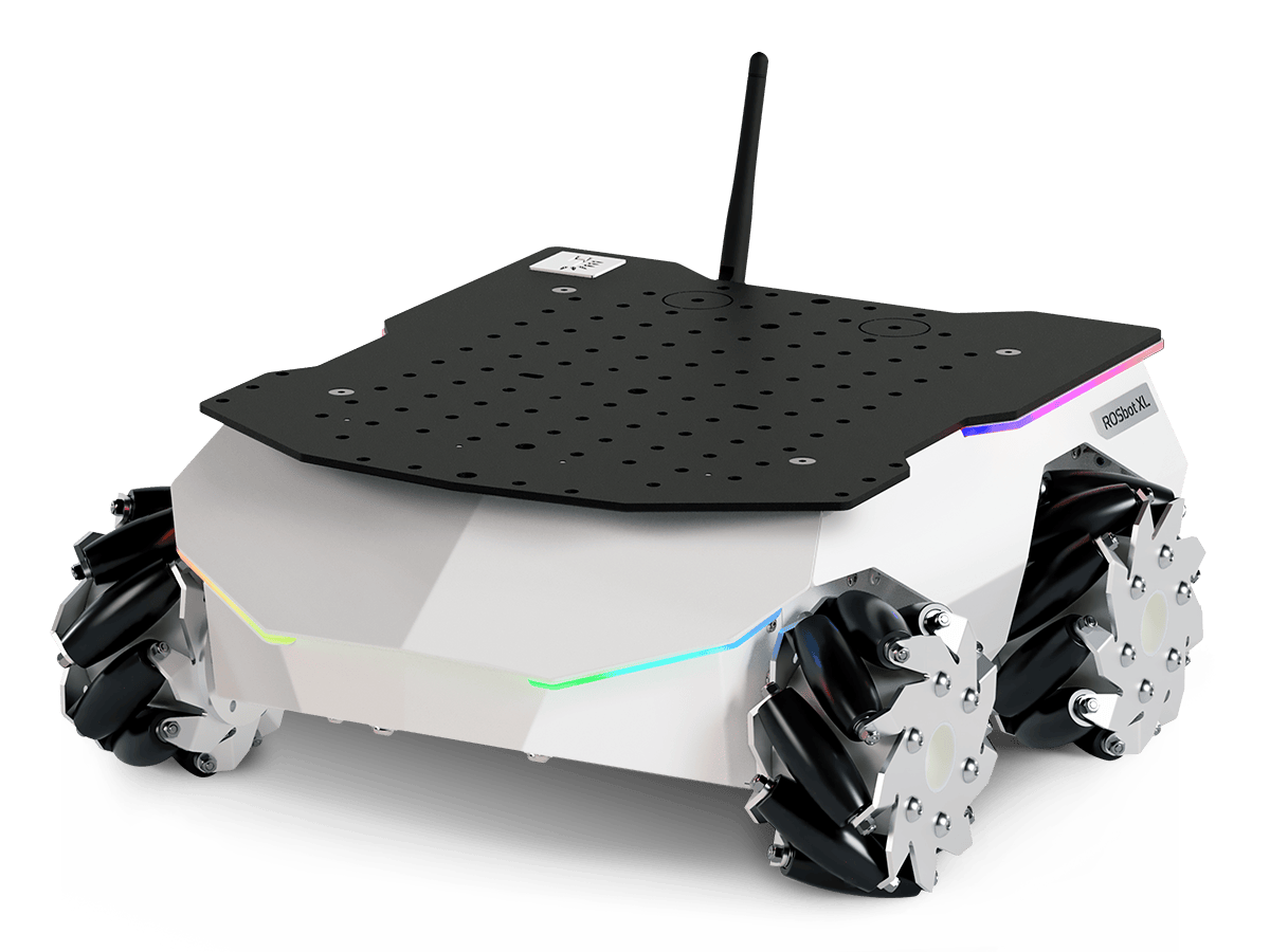
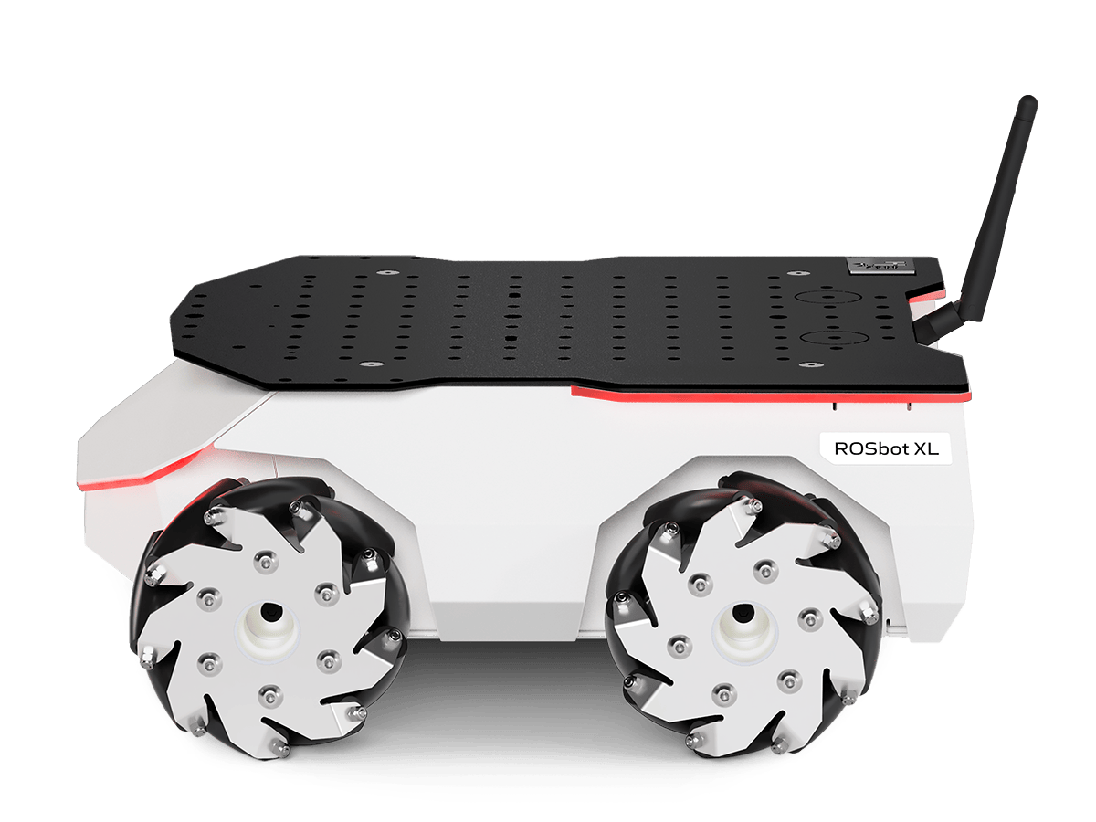
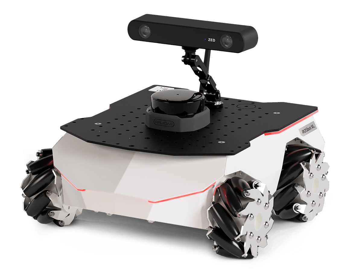
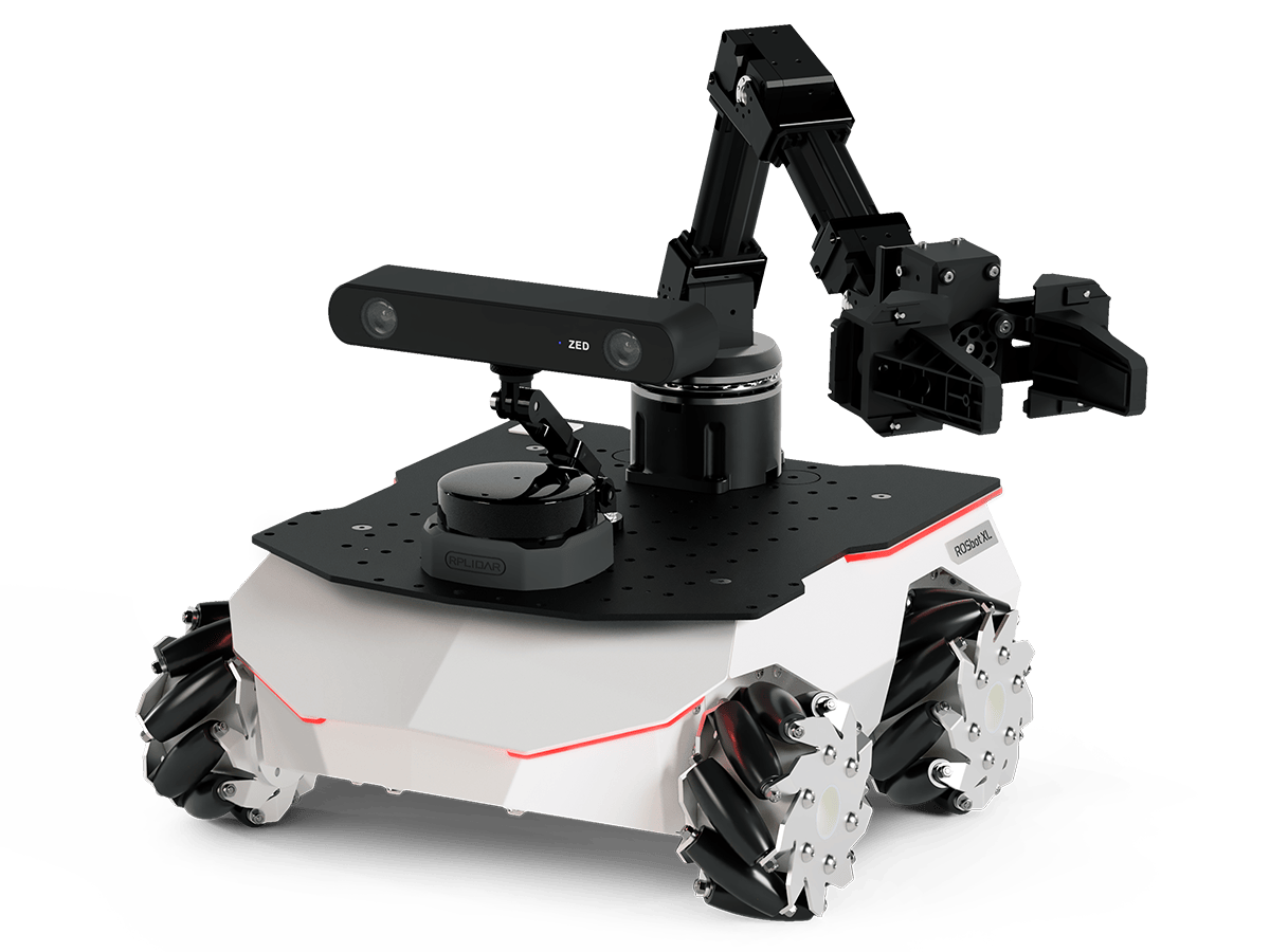
ROSbot XL is an autonomous mobile robot platform equipped with a 4x4 drive, allowing for trouble-free expansion with optional devices such as LIDAR, RGB-D cameras or a manipulator. It offers user-friendly operation with software based on the free and widely developed ROS/ROS 2. All this makes it an ideal choice for both educational and research purposes.
This is a manual. Would you need a quick start guide instead?
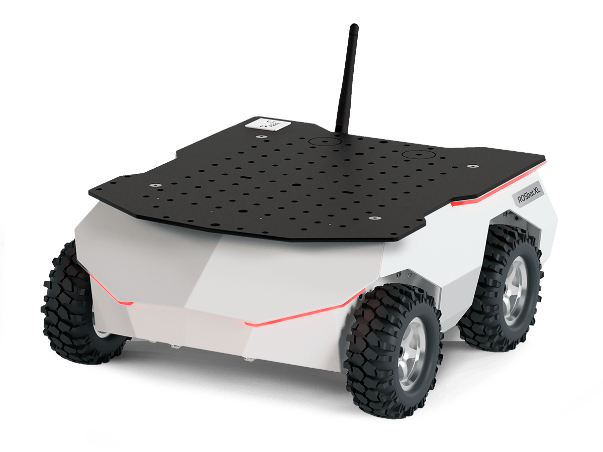
ROSbot is an affordable robot platform for rapid development of autonomous robots. It can be a base for industrial robots, custom service robots, inspection robots and robots working in swarms.
- Aluminium chassis
- 4 x DC motors with quadrature encoders
- IMU
- Built-in USB hub (2 external and 2 internal ports available)
- Built-in Li-Ion 3S battery (11.1V, 7800mAh, 86Wh)
- Power board with advanced energy management (USB-C Power Delivery compatible, protection circuits, contactless charging option)
- Selectable power supply for SBC (5V, 12V, 19V)
- Programmable RGB perimeter LEDs and speaker
- Ethernet-based communication between SBC and STM32F4-based digital controller
- Variety of compatible SBCs (Raspberry Pi, NVIDIA Jetson, Intel NUC i3)
- Universal mounting plate (for LIDARs, robot arms, etc.)
Hardware guide
Specification
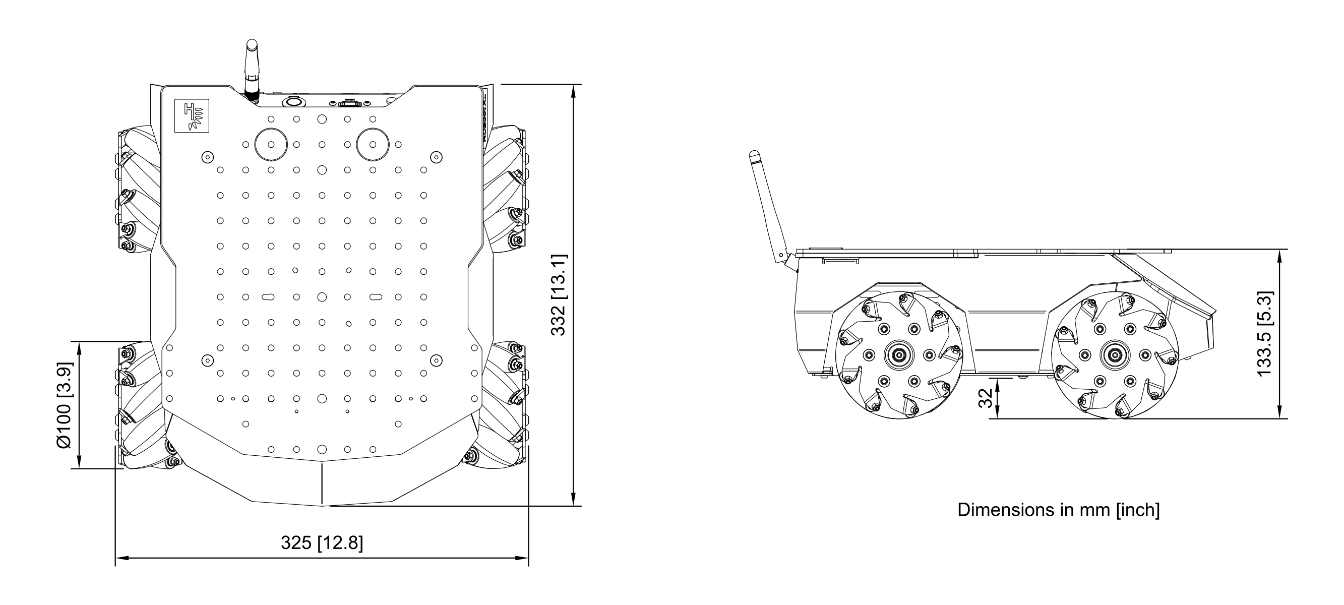
See more detailed drawing here
| Attribute | Description |
|---|---|
| Dimensions without camera and LiDAR | 332 x 325 x 133.5 mm / 12.8 x 13.1 x 5.3 in [L x W x H] |
| Wheel diameter / Clearance / Wheelbase | 100 mm / 32 mm / 170 mm |
| Chassis material | Powder-coated aluminum plate, 1.5 mm thick, top plate 3 mm |
| Weight * | 5380g |
| Maximum translational velocity | 0.8 m/s |
| Maximum rotational velocity | 180 deg/s (3.14 rad/s) |
| Maximum load capacity * | Up to 10 kg / 352 oz |
| Battery life | 2h - 6h |
*With mecanum wheels, RPi4 SBC and no sensors.
Components
| Component | Quantity | Description |
|---|---|---|
| SBC | 1 | Default user computer: Raspberry Pi 5 (8GB RAM). Can also be configured with NVIDIA Jetson Orin Nano (8GB RAM, 250GB SSD) or ASUS NUC 14 ( Intel Core 3 100U 16GB RAM 250GB SSD). |
| Digital Board | 1 | Real-time controller based on STM32F407 microcontroller. |
| Power Board | 1 | USB-C Power Delivery input (12-20V) which supports simultaneous power delivery and battery charging. |
| DC motor | 4 | Xinhe Motor XH-37D, 12VDC nominal, 10000rpm. Maximum mechanical power: 10W, no load speed at the output shaft: 200 rpm, stall torque at the output shaft: 21 kg*cm, stall current: 5.4A, gear ratio: 50 |
| Encoder | 4 | Magnetic, 64cpr, 16 poles |
| IMU sensor | 1 | Intelligent 9-axis absolute orientation sensor BNO055, more details |
| Li-Ion Batteries | 1 | 11.1V 7800mAh 86Wh |
| Antenna | 1 | Connected directly to Wi-Fi module. |
| Speaker | 1 | Driven from Digital Board or from SBC (selectable source). |
| Accessories included | - | Wireless pad, USB-C charger (65W), two sets of wheels (4x regular and 4x mecanum), adjustable camera mount. |
ROSbot XL is available in ready to use configuration packages adjusted for different applications.
Block diagram
A graphic representation of ROSbot XL components and connections between them. The detailed version: [PDF] ROSbot XL block diagram.

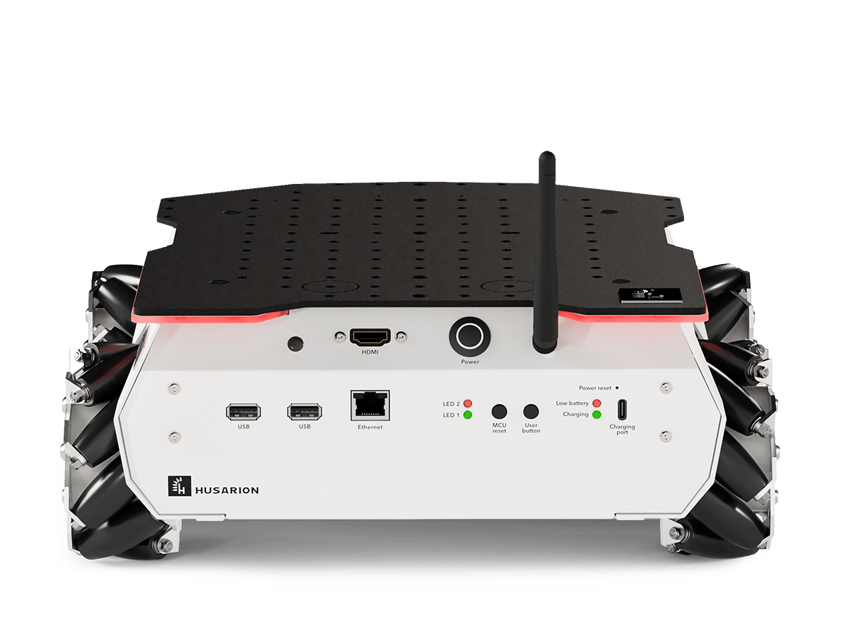
Rear panel description

| Item | Quantity | Description |
|---|---|---|
| Antenna connector | 1 (2) | Wi-Fi antenna RP-SMA socket. Required for Wi-Fi connectivity. For some SBCs, 2 antennas are used. |
| USB | 2 | USB 2.0 host ports from SBC. |
| HDMI | 1 | HDMI output from SBC. |
| Ethernet | 1 | Ethernet port. Connected with internal SBC via integrated 2-port switch. |
| Power button | 1 | Turns ROSbot ON or OFF. Hold for 1.5 seconds to turn robot on, 0.5 seconds to turn off. |
| LEDs | 4 | LED1(green), LED2(red), LED3(green), LED4(red) |
| DB Reset | 1 | Button used for reset digital board. |
| PB Reset | 1 | Hidden button used for reset power board. |
| User button | 1 | Programmable button. |
| USB type C power input | 1 | USB-C Power Delivery input (12-20V) which supports simultaneous power delivery and battery charging. |
LED statuses
| LED | color | State | Message |
|---|---|---|---|
| LED1 | green | ON | Firmware finished booting |
| LED2 | red | Toggling | Error of RTOS'a or microROS |
| Low bat | red | ON | Battery level is low |
| Charging | green | Toggling | Battery is charging |
| Charging | green | ON | Battery is fully charged |
| Power button | white | ON | Power is ON |
| Power button | white | Toggling | System is shutting down |
| Pixel panels | RGB | Programmable | In default shows looped animation |
Battery & charging
An internal battery is disconnected during transport. Connect the battery plug before the first use. You need to unscrew the battery cover first. See Quick start for more detailed guide.
When you receive the robot, the battery level should be about 30-40%. You do not need to perform any initial procedures, however, we recommend to begin the first software setup with the charger plugged. The battery will charge to a higher level and you avoid draining it to zero, which is not recommended just after the storage/transport period. The current battery voltage can be read from the ROS API. The voltage should never fall under 9V, which is the "0%" level, and should not exceed 12.6V, which is "100%" level.
Battery & charger parameters
| Parameter | Value | Comment |
|---|---|---|
| Battery type | Li-Ion | 3S configuration |
| Battery voltage & capacity | 11.1V 7800mAh | 86.5Wh |
| Max. discharge current | 8A | |
| Max. charge current | 2.7A | limited by robot |
| Charging temp. range | 0°C - 45°C | |
| Operating temp. range | -20°C - 60°C | |
| Charger | 20V 65W | PD2.0/3.0 compatible |
Charging
ROSbot XL integrates an on-board battery charger. The charging process starts automatically after connecting the power adapter and terminates when the battery is full. The low battery level is indicated by "Low bat" LED on the rear panel.
We strongly recommend to use the power adapter delivered with the robot. However, it is also possible to supply/charge the robot with any adapter that is compatible with Power Delivery (PD2.0/PD3.0) and provides 15V or 20V output with the minimum 3A current (the current draw is internally limited to 2.8A).
There are 4 possible modes of operation:
- a) Active, battery only.
- b) Active, battery + power adapter. In this mode the robot can be used and charged simultaneously. The battery is used only when the robot current consumption exceeds the power adapter maximum current.
- c) Inactive (powered off), battery only. Robot in this state does not draw current from battery and can remain in this state for weeks. The battery state should be checked every 6-8 weeks and recharged if the battery level is below 25%. For a prolonged storage, the best battery level is 40-50%.
- d) Inactive, battery + power adapter. In this state the battery charges with the maximum speed (2.5A maximum). Robot can be switched on at any time, with transition to mode "b)".
The battery charging process should take about 5-6 hours in d) mode (from 0% to 100%).
User compartment
ROSbot XL allows the user access to its interior by default. This chapter describes the items (connectors, switches, cables) that can be utilized by user. Please read it carefully before making any changes inside the robot. Please keep in mind that despite modifications are allowed, you need to have a basic experience with electronic circuits/boards to avoid damage. The interior is not protected in any way and it is very easy to make a damage to the robot. Damages made by user are not covered by our limited warranty.
Digital board items
A digital board is the big, white PCBA, located on the rear end of the robot.
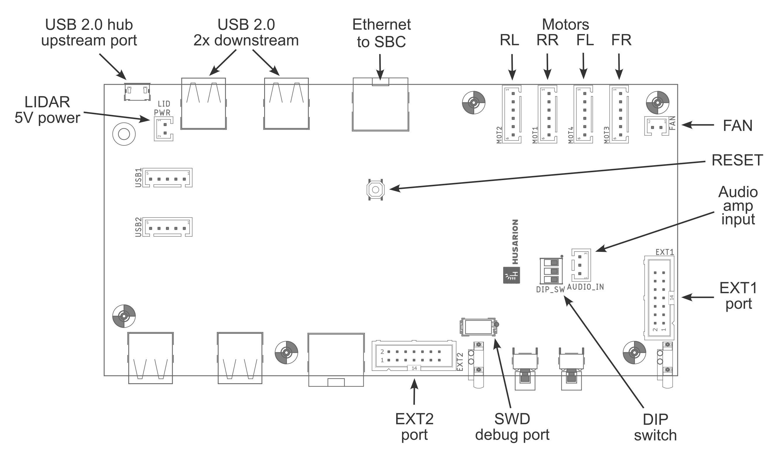
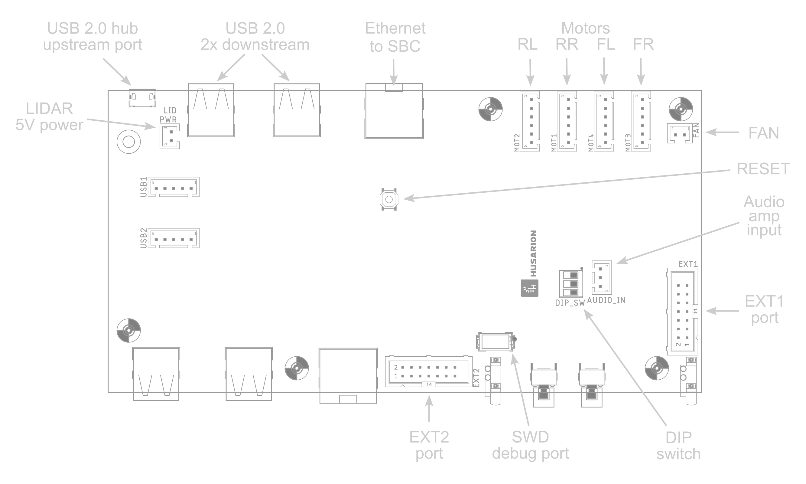
DIP switch on Digital Board (DIP_SW)
The switch sections are numbered from the left:

| Section | Function | OFF setting | ON setting |
|---|---|---|---|
| 1 | Speaker source | audio source = SBC (via CON19) | audio source = MCU |
| 2 | none | for future use | for future use |
| 3 | MCU BOOT0 | MCU boot from FLASH | MCU bootloader active |
Analog audio input (AUDIO_IN)
Analog audio input of integrated amplifier and speaker. Designed for SBC audio output connection. DIP_SW section 1 shall be set to OFF when this input is used. If you ordered ROSbot XL with Raspberry Pi 4, this cable is already connected.

| Pin | Signal | Input name | Source node |
|---|---|---|---|
| 1 | GND | Reference/shield ground | - |
| 2 | IN+ | Differential input positive | Left channel |
| 3 | IN- | Differential input negative | Ground |
Usually SBCs do not have differential audio output. Therefore, please use GND as a shield, IN+ as a signal input and IN- as a ground connection on the SBC side. This "pseudo-differential" connection helps with noise limiting. The connector plug type is JST XHP-3.
Extra GPIO - bank 1 (EXT1)
The EXT1 connector contains a few GPIOs that can be used by more experienced users. All signals are in 3.3V logic and all of them have 220R resistor in series.

| Pin | STM32 pin | Signal name | Comment |
|---|---|---|---|
| 1 | PG3 | EXT_GPIO2 | |
| 2 | PG2 | EXT_GPIO1 | |
| 3 | PE6 | EXT_PWM2 | |
| 4 | PE5 | EXT_PWM1 | |
| 5 | PG14 | USART6_TX | |
| 6 | PG9 | USART6_RX | |
| 7 | PB6 | I2C1_SCL | External pull-up needed |
| 8 | PB7 | I2C1_SDA | External pull-up needed |
| 9 | PB5 | SPI1_MOSI | |
| 10 | PA5 | SPI1_SCK | |
| 11 | PA6 | SPI1_MISO | |
| 12 | — | +3V3_PROT | Power supply output. OC protection at 500mA |
| 13 | — | GND | Ground |
| 14 | — | +5V_PROT | Power supply output. OC protection at 500mA |
Extra GPIO - bank 2 (EXT2)
The EXT2 connector contains a few GPIOs that can be used by more experienced users. All signals are in 3.3V logic and all of them have 220R resistor in series. In addition, the pins with ADC (Analog-to-Digital Converter) function have 100nF capacitor closer to the MCU.

| Pin | STM32 pin | Signal name | Comment |
|---|---|---|---|
| 1 | — | GND | |
| 2 | — | BOOT0 | pull-down on board |
| 3 | PB14 | EXT_PWM3 | |
| 4 | — | NRST | pull-up on board |
| 5 | PF3 | EXT_ADC1 | |
| 6 | PF4 | EXT_ADC2 | |
| 7 | PF5 | EXT_ADC3 | |
| 8 | PG4 | EXT_GPIO3 | |
| 9 | PC9 | I2C3_SDA | External pull-up needed |
| 10 | PA8 | I2C3_SCL | External pull-up needed |
| 11 | PD1 | CAN1_TX | External transceiver needed |
| 12 | PD0 | CAN1_RX | External transceiver needed |
| 13 | — | +3V3_PROT | Power supply output. OC protection at 500mA |
| 14 | — | +5V_PROT | Power supply output. OC protection at 500mA |
The connector type for both EXT1 and EXT2 ports is a commonly-known ribbon IDC cable connector, with pin-to-pin pitch 2.54mm (0.1") and the ribbon cable pitch 1.27mm (0.05"). The example model is Harting 09 18 514 5813 58U.
Power board items
A power board is the vertically oriented, white PCBA, located in parallel to the right side of the robot. Below you can see the fragment of it - the upper left corner.
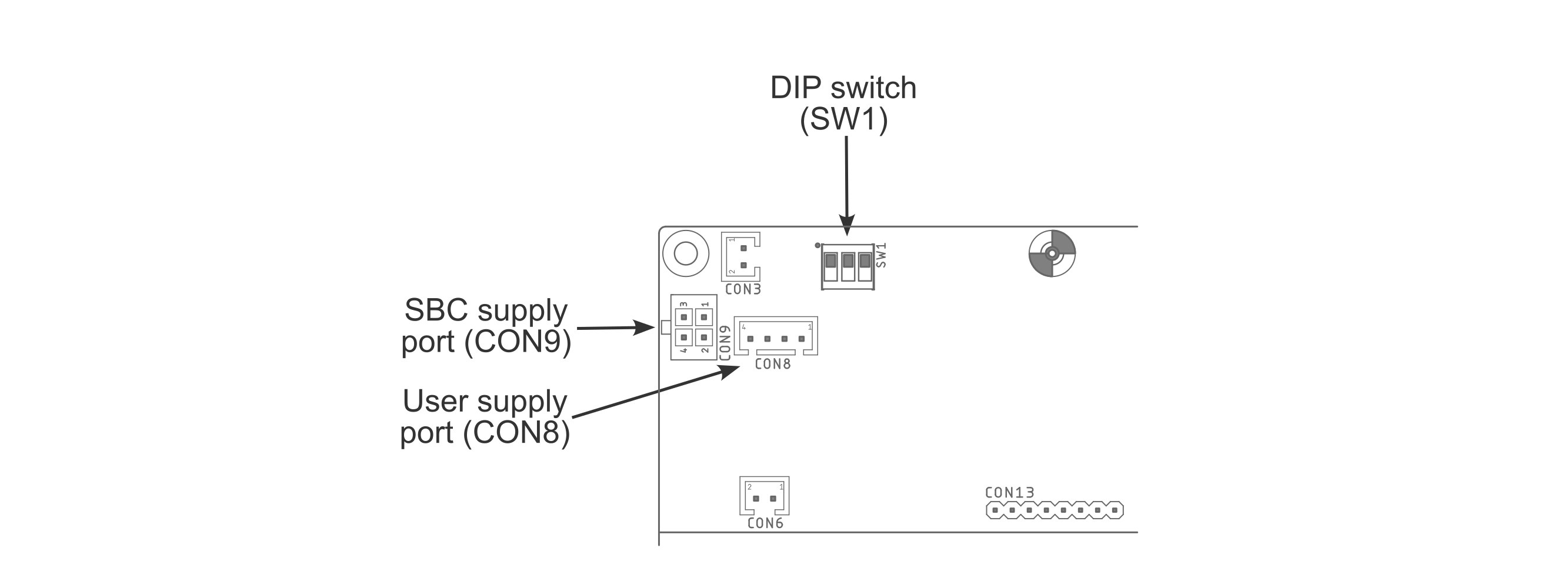
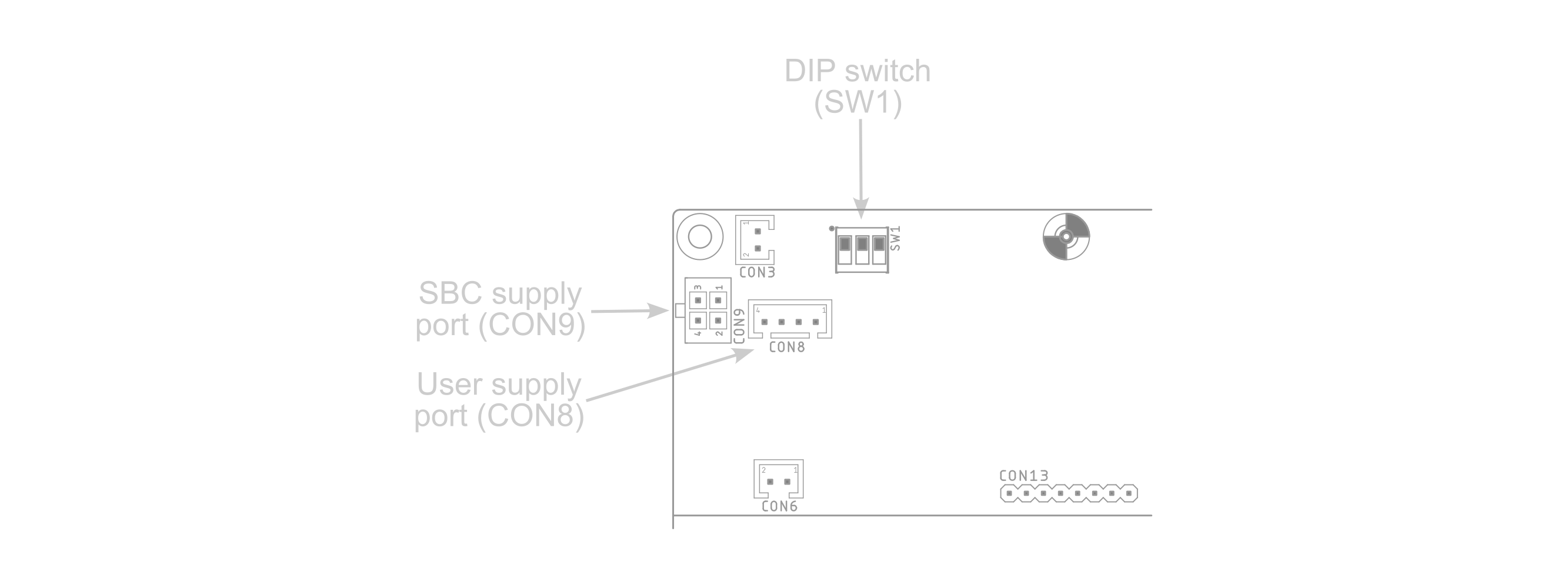
There are several items which need a better description:
DIP switch on Power Board (SW1)
This switch changes the SBC supply voltage available on SBC supply port (CON9, pin 2) and User supply port (CON8, pin 2). The switch sections are numbered from the left:

| Section | Function | Default setting | Comment |
|---|---|---|---|
| 1 | none | OFF | do not change |
| 2 | none | ON | do not change |
| 3 | SBC supply 19V enable | OFF | Turn to ON for 19V output. Keep OFF for 12V. |
SBC supply port (CON9)
This connector is used to supply the user computer. If you purchased ROXbot XL with the chosen user computer, the power supply for this SBC is already connected here. The pinout may be useful if you would like to install or replace the SBC by yourself.

| Pin | Signal | Max current | Comment |
|---|---|---|---|
| 1 | GND | 5A | |
| 2 | +12V/+19V | 4.75A/3A | set with DIP switch |
| 3 | Vbat2 | 5A | 9V ... 12.6V |
| 4 | +5V | 5A |
Compatible plug housing: Molex 43025-0400. Compatible plug terminal: Molex 43030-0007
User supply port (CON8)

| Pin | Signal | Max current | Comment |
|---|---|---|---|
| 1 | GND | 3A | |
| 2 | +12V/+19V | 3A | set with DIP switch |
| 3 | Vbat1 | 3A | 9V ... 12.6V |
| 4 | +5V | 3A |
The connector plug type is JST XHP-4.
The +5V and +12/19V line are shared between CON8 and CON9. The total current for both cannot exceed the maximum current for CON9. The Vbat1/Vbat2 lines are shared with all other circuits, including motors, +5V, +12V/+19V. Therefore, depending on the total power usage, the maximum current on Vbat1/Vbat2 can be lower than specified here.
Fan
The perforated top cover provides effective cooling for the robot. The left side wall of the robot's case features a chassis fan to further improve cooling for demanding computers (such as the ASUS NUC). The fan does not run all the time, but only when the air temperature inside exceeds 35 degrees.
CAD models
To facilitate the work with the project based on ROSbot XL platform, we have prepared CAD models for download in three extension formats:
- STEP - all variants zipped [9,5MB] - contains models with mecanum or regular wheels, collision model, PCBs model and a complete model with all part variants.
- STL - all variants zipped [3,3MB] - contains models with mecanum, regular or no wheels and a collision model, in two quality levels.
- F3D - Autodesk 360 Fusion model [3,2MB] - contains a complete model with selectable features.
Software
Software packages for ROSbot XL are available in the rosbot_xl_ros repository.
Docker containers
The recommended way of running software on ROSbot XL is using docker containers, here you can find the list of available containers.
Speaker
The ROSbot XL is equipped with a speaker on board connected to the SBC. Depending on the SBC, you may test the speaker or play any audio file. First of all in the terminal export the audio device.
- Jetson Orin
- Raspberry Pi
- Other
speaker-test -D plughw:$(aplay -l | awk -F'[:[]' '/USB Audio Device/ {gsub(/ /, "", $2); print $2",0"}') -c2 -t wav -l 1
export AUDIODEV=hw:$(aplay -l | grep "Headphones" | sed -n 's/card \([0-9]\+\).*device \([0-9]\+\).*/\1,\2/p')
export AUDIODEV=hw:$(aplay -l | grep "USB Audio Device" | sed -n 's/card \([0-9]\+\).*device \([0-9]\+\).*/\1,\2/p')
If your audio device is exported check the speaker with playing the sine.
play -n synth 0.6 sin 180
To play the music or recorded audio use aplay command:
aplay <audio_file>
ROS / ROS 2 API
Detailed information about content of rosbot package for ROS2.
Control
Gamepad
After running the ROSbot XL Manipulation Package, you should be able to control the manipulator. The easiest way to move the manipulator is to connect a gamepad and steer the robot. The graphic below shows how to steer the manipulator using a gamepad.
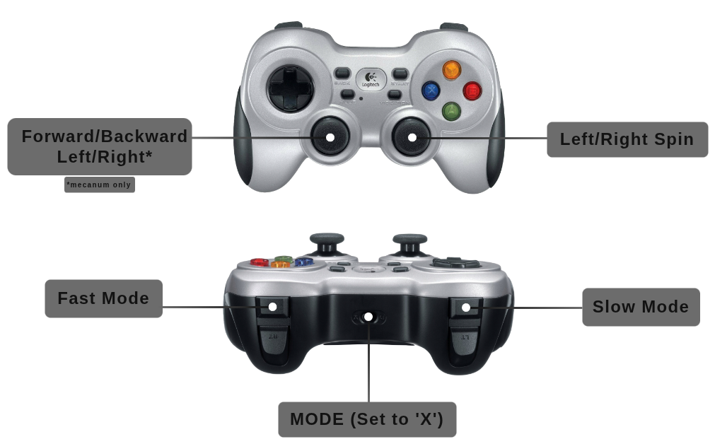
Drive controls (cmd_vel) are defined in rosbot_joy/config/config.yaml. The manipulator gamepad mappings (XL only) are hardcoded in rosbot_moveit/src/joy2servo.cpp.
ROS API
Namespace policy
Everything below is published under /<namespace>/ when the namespace
launch arg (or ROBOT_NAMESPACE env) is set. Intentional globals:
/tf,/tf_static— bridged via tf_namespace_bridge./parameter_events,/rosout— ROS 2 infra./clock— sim only.
Hard-coded, no runtime opt-out. HW uses push_ros_namespace, sim uses URDF
<remapping> for the controller_manager surface — see
Namespacing and multirobot.
Enforced by
test_namespace_isolation.py.
Available Nodes
| 🤖 | 🖥️ | NODE | DESCRIPTION |
|---|---|---|---|
| ✅ | ✅ | controller_manager | Controller Manager performs two main functions. First, it manages controllers and their required interfaces, handling tasks like loading, activating, deactivating, and unloading. Second, it interacts with hardware components, ensuring access to their interfaces. controller_manager/controller_manager |
| ✅ | ✅ | differential_drive_controller / mecanum_drive_controller | The controller managing a mobile robot with a differential or omni drive (mecanum wheels). Converts speed commands for the robot body to wheel commands for the base. It also calculates odometry based on hardware feedback and shares it.DiffDriveController or MecanumDriveController diff_drive_controller/diff_drive_controller |
| ✅ | ✅ | ekf_node | Used to fuse wheel odometry and IMU data. Parameters are defined in rosbot_localization/config/config.yaml robot_localization/ekf_node |
| ❌ | ✅ | /gz_bridge | Transmits Gazebo simulation data to the ROS layer ros_gz_bridge/parameter_bridge |
| ❌ | ✅ | gz_ros_control | Responsible for integrating the ros2_control controller architecture with the Gazebo simulator. gz_ros2_control/gz_ros2_control |
| ✅ | ✅ | imu_broadcaster | The broadcaster to publish readings of IMU sensors imu_sensor_broadcaster/imu_sensor_broadcaster |
| ✅ | ❌ | imu_sensor_node | The node responsible for subscriptions to IMU data from the hardware rosbot_hardware_interfaces/rosbot_imu_sensor |
| ✅ | ✅ | joint_state_broadcaster | The broadcaster reads all state interfaces and reports them on specific topics joint_state_broadcaster/joint_state_broadcaster |
| ✅ | ✅ | robot_state_publisher | Uses the URDF specified by the parameter robot*description and the joint positions from the topic joint*states to calculate the forward kinematics of the robot and publish the results using tf robot_state_publisher/robot_state_publisher |
| ✅ | ❌ | rosbot_system_node | The node communicating with the hardware responsible for receiving and sending data related to engine control rosbot_hardware_interfaces/rosbot_system |
| ❌ | ✅ | rosbot_gz_bridge | Transmits data about the robot between the Gazebo simulator and ROS. ros_gz_bridge/parameter_bridge |
| ✅ | ❌ | rosbot_mcu | Microcontroller unit (MCU) communication node. Default: rosbot_mavlink_bridge (MAVLink). With backend:=microros it is replaced by the micro_ros_agent node, which speaks XRCE-DDS to the MCU instead. [rosbot_mavlink_bridge/rosbot_mavlink_bridge] |
Available Topics
| 🤖 | 🖥️ | TOPIC | DESCRIPTION |
|---|---|---|---|
| ✅ | ✅ | cmd_vel | Sends velocity commands for controlling robot motion (use_stamped_vel: true). geometry_msgs/TwistStamped |
| ✅ | ✅ | diagnostics | Contains diagnostic information about the robot's systems. diagnostic_msgs/DiagnosticArray |
| ✅ | ✅ | dynamic_joint_states | Publishes information about the dynamic state of joints. control_msgs/DynamicJointState |
| ✅ | ✅ | imu/data | Broadcasts IMU (Inertial Measurement Unit) data. sensor_msgs/Imu |
| ✅ | ✅ | joint_states | Publishes information about the state of robot joints. On hardware the effort field carries wheel motor torque (measured on ROSbot XL rev 1.2, back-EMF estimate otherwise); in simulation effort is NaN. sensor_msgs/JointState |
| ✅ | ✅ | joy | Publishes joystick input data. sensor_msgs/Joy |
| ✅ | ✅ | odometry/filtered | Publishes filtered odometry data. nav_msgs/Odometry |
| ✅ | ✅ | odometry/wheels | Provides odometry data from the base controller of the ROSbot XL. nav_msgs/Odometry |
| ✅ | ✅ | robot_description | Publishes the robot's description. std_msgs/String |
| ✅ | ✅ | scan | Publishes raw laser scan data. sensor_msgs/LaserScan |
| ✅ | ✅ | set_pose | Changes the robot's odometry/filtered pose. geometry_msgs/PoseWithCovarianceStamped |
| ✅ | ✅ | tf | Publishes transformations between coordinate frames over time. tf2_msgs/TFMessage |
| ✅ | ✅ | tf_static | Publishes static transformations between coordinate frames. tf2_msgs/TFMessage |
There are also additional topics related with the ROSbot firmware. For more information about them, please refer to the ROSbot Firmware documentation.
Available Services
| 🤖 | 🖥️ | SERVICE | DESCRIPTION |
|---|---|---|---|
| ✅ | ❌ | led_strip/enable | ROSbot XL only. Enables (data: true) or disables (data: false) the LED strip animation. While disabled the led_strip_manager node neither computes nor publishes the led_strip image. std_srvs/SetBool |
Packages
One-line purpose per package; full detail (launch flows, internals) in ARCHITECTURE.md.
| Package | Description |
|---|---|
rosbot | Meta-package — pins sibling repos via *.repos, no code. |
rosbot_bringup | Hardware entry point: per-model bringup + MCU backend (MAVLink default / micro-ROS). Local-only. |
rosbot_controller | ros2_control setup — spawns drive, IMU and joint-state controllers (plus the manipulator on XL). |
rosbot_description | URDF/xacro for hardware and simulation, robot configurations, robot_state_publisher. |
rosbot_gazebo | Gazebo simulation launch and robot spawning. Local-only. |
rosbot_hardware_interfaces | C++ ros2_control plugins (RosbotSystem, RosbotImuSensor) — the firmware ABI. |
rosbot_joy | Joystick teleop for driving (joy_node + teleop_twist_joy). |
rosbot_localization | EKF fusing wheel odometry + IMU → odometry/filtered. |
rosbot_moveit | MoveIt manipulation for the OpenMANIPULATOR-X (XL only) — see MANIPULATOR.md. |
rosbot_utils | Utilities: firmware flashing, robot configuration, udev rules, battery alert, LED strip. |
Operating System image reinstallation
In some cases you will need to restore ROSbot system to its default settings:
- in case of accidental damage of the system,
- to update the OS (it can be updated remotely, but flashing the microSD card can be easier sometimes),
- to clear all user changes and restore factory settings.
This process will differ depending on ROSbot version that you have. Find the full instruction here
Reference projects
Running ROS natively is fine for relatively small projects. For more complex ones, the full dockerized setup is a better approach.
Find available projects below:
| link | description |
|---|---|
| rosbot-xl-gamepad | Control the robot manually using a Logitech F710 gamepad |
| rosbot-xl-telepresence | Controlling ROSbot XL over the Internet with a live video feed |
| rosbot-xl-autonomy | Autonomous mapping & navigation demo for ROSbot XL. Using navigation2 and slam_toolbox |
| rosbot-xl-manipulation | Using ROSbot XL with OpenMANIPULATOR-X. Read more about this project in the dedicated tutorial (including Gazebo simulation) |
ROS 2 Tutorials
ROS 2 (Robot Operating System 2) offers libraries and tools designed to aid in developing robotic applications.
We offer a collection of ROS 2 Tutorials for the ROSbot XL platform, providing a hands-on introduction to ROS 2 suitable for both beginners and advanced users. These tutorials can be run on any ROSbots, either on a physical unit or in the Gazebo simulation environment, covering topics from basic navigation to complex operations. Here is the list of ROS 2 tutorials available for ROSbot XL:
- ROS 2 Introduction
- Creating Nodes - Messages
- Creating Nodes - Services
- Kinematics and Visualization
- Track object with OpenCV
- Running ROS 2 on Multiple Machines
- Transformation
- SLAM
- Navigation
- Exploration
Docs and links
All helpful documents and links in one place: