Wireless Charger
The Panther v1.2 platform can be configured with WCH01 and WCH02 options, providing an efficient and hassle-free charging with WiBotic's wireless charging equipment for mobile robots (AMR, UGV etc.). This manual serves as your comprehensive guide to seamlessly integrating and utilizing the wireless charging system on your Panther.
The charging system is already configured before shipping and you do not need to configure it before using the system. The only thing to do is to assemble the Ground Station and, after levelling of the Ground Station, dock the robot in the correct place in front of the station.
In this manual, you'll find basic instructions, step-by-step procedures, and essential safety precautions. To ensure optimal performance and longevity of your wireless charging equipment, or to get more info how to use the extended functionality of WiBotic Wireless Power System, we strongly recommend to read the original WiBotic User Guide.
Wireless Charging System Description
Wireless charging basically replaces a standard single channel charger, while adding the ability to operate the device completely autonomously or remotely. Wireless charger can charge the robot to 80% in 4 hours, and to 100% in less than 7 hours.
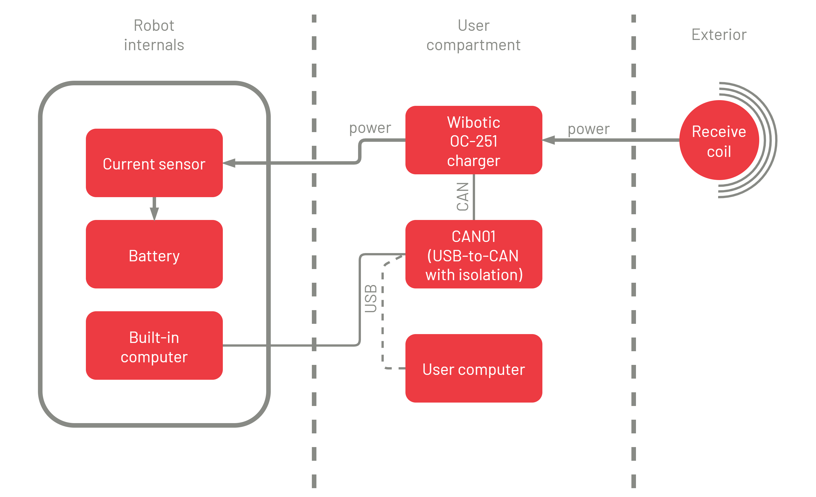
This system comprises two main components. The Receiver is installed in the robot and another is the Ground Station for charging the robot. WCH01 receiver is required for each robot in your fleet but you don't necessarily need as many ground stations as robots. The wireless charger supports the same power (about 200W) as the conventional wired charger, which is supplied with the robot as a backup charger.
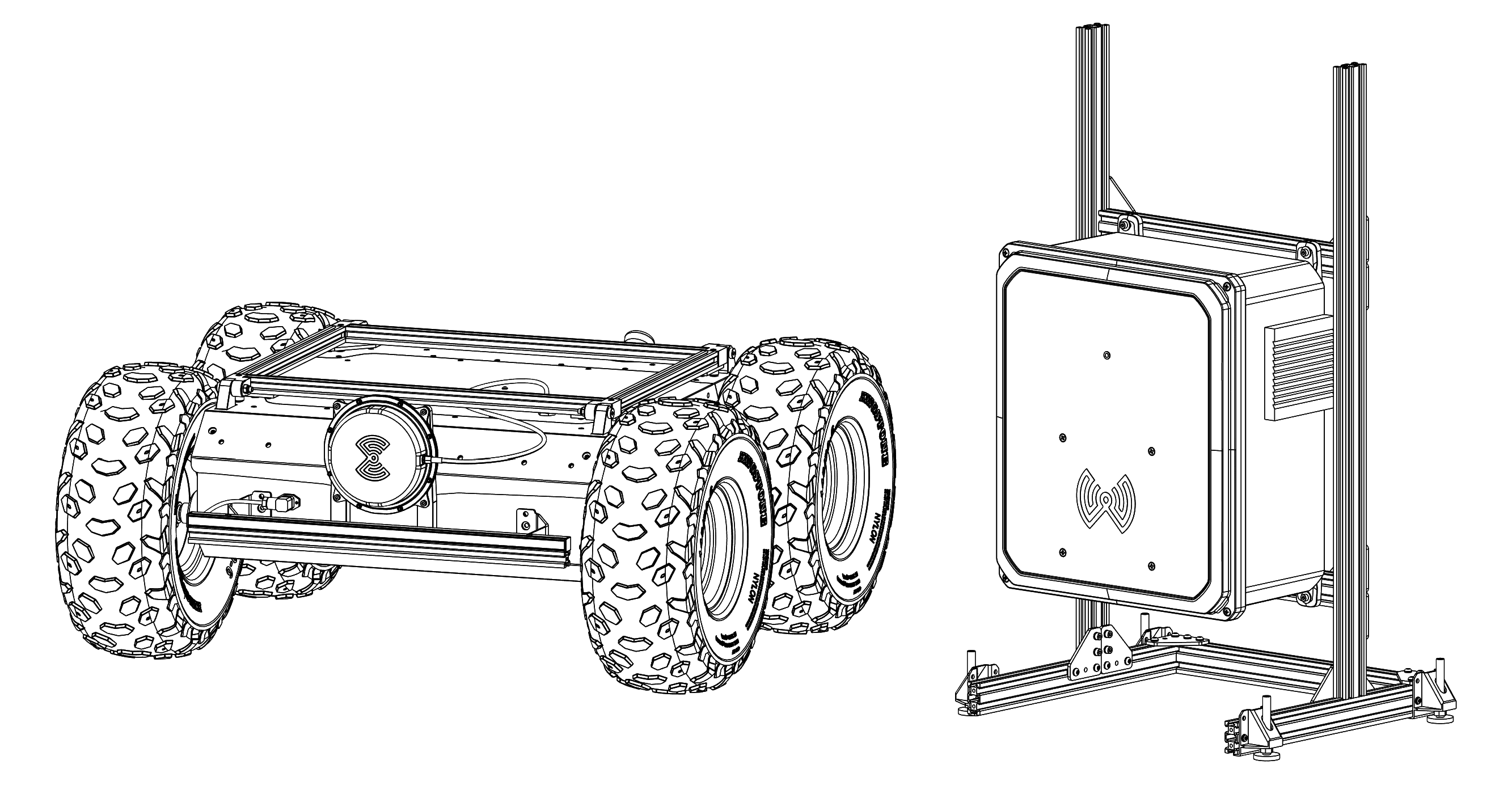
WCH01 - Receiver
A set that integrates the Receive Coil (antenna), mounted on the front of the robot, and the On-board Charger unit that delivers the received energy to the Panther's Battery. It's connected and ready to facilitate wireless charging, ensuring your mobile platform stays powered up and operational without the hassle of manual intervention.
Receive Coil is installed on the front bumper of the robot. The coil placement is important and should not be changed unless you have consulted with the Husarion support team. This is due to the fact that the transmit and receive coils are tuned to work with metal components, such as the Panther aluminum covers, located close to the coils. The electrical energy from the coil goes through the cable to the On-board charger.
The Receive Coil needs to be placed in front of the Transmit Coil in the Ground Station to allow charging. The maximum distance for initiation of the charging process is 5cm when both coils are aligned coaxially. The recommended distance is below 3cm. The exact Transmit Coil location is marked with the large, blue symbol (WiBotic's logo) on the Transmitter Unit. Thanks to that you can easily align both coils.
On-board Charger is installed inside Panther, in the User Compartment. It carries out two functions: converts the AC power signal from the Receive Coil to the DC voltage, and automatically controls the Battery charging process.
CAN interface - the On-board Charger can provide an optional, additional data via CAN interface. The CAN to USB converter is already connected to the Built-in Computer, via USB connector available on Communication Panel. For now, the software that handles this data is not supported yet. If you need the additional information about the charging process, other than the Battery charging current and voltage, you can simply connect this USB adapter to the User Computer instead of Built-in Computer and follow the WiBotic User Guide for an introduction to the CAN communication interface of On-board Charger.
WCH02 - Ground Station
The Ground Station assembly contains a Transmitter Unit with embedded Transmit Coil (antenna), mounted on aluminum frame. The Ground Station complements the Panther platform unit, enabling efficient charging of your mobile robot wherever it operates. Before use, it's essential to assemble the Stand because it is shipped in disassembled state.
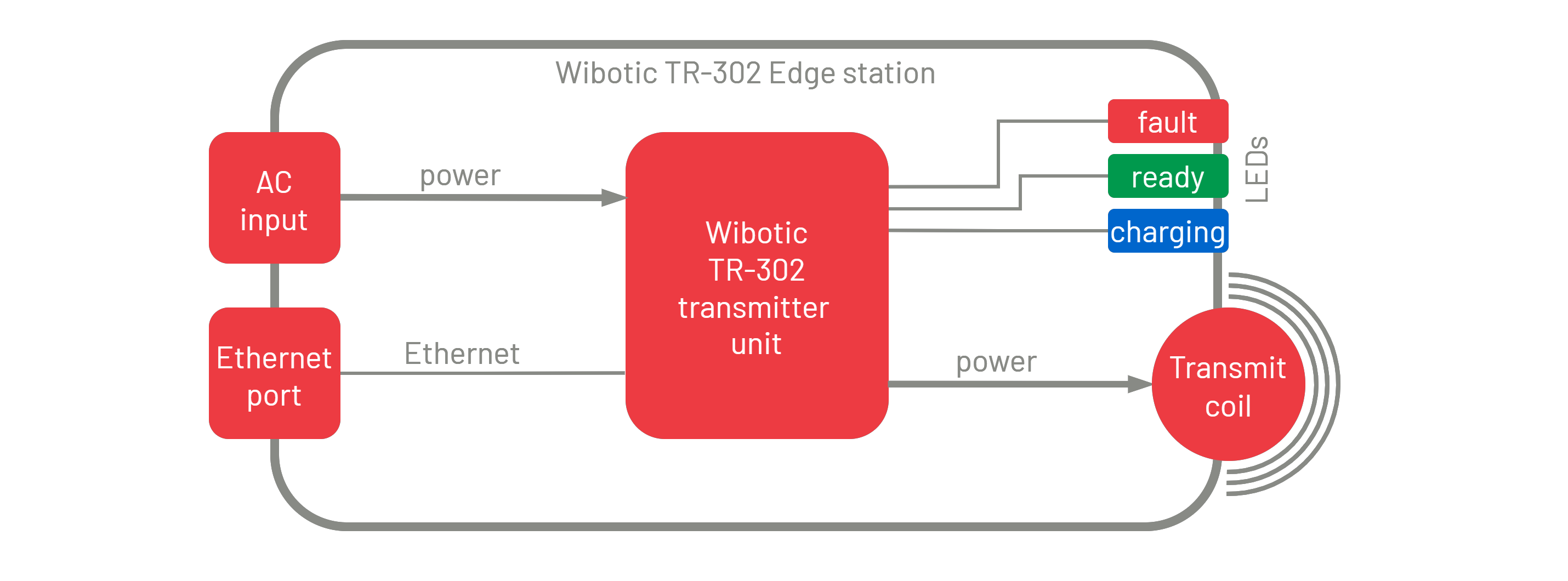
Transmitter Unit is a part of the WiBotic system called TR-302 Edge mounted on the Stand. It integrates the Transmit Coil just behind the blue WiBotic logo on the front, which also marks the position of the coil. Transmitter Unit needs to be connected to the mains voltage and can be also connected to a computer using Ethernet port. The sealed enclosure contains a slightly modified TR-302 transmitter inside - it is important to know when you are reading the WiBotic User Guide.
LED indicators are located above the Transmit Coil and shows the transmitter status:
| LED | Fault | Ready | Charging | Status |
|---|---|---|---|---|
| color | RED | GREEN | BLUE | - |
| off | off | off | off | |
| off | blinking | off | powered on, charging disabled | |
| off | on | off | ready to charge | |
| off | on | on | charging | |
| on | off | off | alarm condition |
Ethernet port - you can optionally use it to configure and monitor the functionality of the Ground Station. See WiBotic User Guide for more details. Would you rather avoid it? Do not worry, we have configured it for you before shipping.
Stand - and aluminum frame that holds the Transmitter Unit in the correct position above the ground. If you need, you hang the Transmitter Unit on the wall and do not use the Stand. In that case, alignment of the coils will be more difficult.
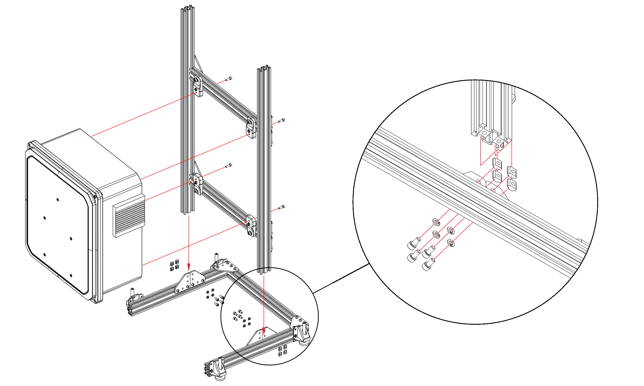
Ground Station Assembly
Let's dive into the specifics of assembly and operation to get your wireless charging system up and running in no time. The package of WCH02 module contains:
- Horizontal base with legs for height adjustment and leveling.
- A vertical frame that is used to roughly adjust the station's height above the ground.
- Plastic housing for the WiBotic transmitter.
- Transmitter power cable.
- A bag with screws, containing:
- 8x M5x10 Bolt with hexagon socket, fillister head bolt,
- 4x M5x16 Bolt with hexagon socket, fillister head bolt,
- 8x M5 Spring lock washer with bent end,
- 8x M5 Hammer nut for V-slot profiles.
Step 1 - In the aluminum plates at the top of the horizontal base, place a short screw and washer in the eight holes on the center side of the base, and a nut on the other side.
Step 2 - Slide the vertical frame onto the nuts as shown in the figure below and tighten the screws.
Step 3 - Using four long screws, attach the transmitter box to the platic brackets on the vertical frame.
Step 4 - Adjust the base of the station so that it remains stable in the target place. Place the Panther directly in front of the transmitter.
Step 5 - Make sure that the WiBotic blue logo on the transmitter is aligned (at the same height) that the receiver coil mounted to Panther. If not, please adjust the transmitter height with adjustable legs of the station or by adjusting the height of the transmitter on the base.
Step 6 - Connect the transmitter to the power supply. The charging process should start immediately. If Panther is active, you should see the charging animation displayed on LEDs and the blue LED indicator on the Transmitter Unit should be lit.
After this one-time, manual positioning, next time you can just drive the robot to the same position and the charging will start automatically.
Important Notes
It is impossible to drive the robot during the charging process. Any movement may disturb the charging process.
On-board Charger standby current. The On-board Charger (WCH01 part) is directly connected to the Battery, inside the Panther robot and it consumes a small current of about 5mA all the time. This power is needed to supply the On-board Charger receiver circuits to be able to recognize the Ground Station (Transmitter Unit) automatically, and immediately start the charging process. However, if you plan to not use Panther for a prolonged time (more than one month) please remember to turn the Battery Switch to the OFF position. In this way the On-board Charger will be disconnected from the Battery and the mentioned, small current will no longer discharge the Battery.
Use of wired charger. If you need to charge Panther using the regular, wired charger, you can ignore the wireless charging system and simply connect the wired charger to the Charging Socket on the Rear Panel. There is one exception though:
Do not use the wired charger when the mobile platform is docked to the Ground Station (Transmitter Unit). It may cause blowing the Battery protection fuse or even damaging the Battery.
Single channel (battery) charging. Please note that due to the single-channel output of the wireless charging system, it is only possible to charge one battery (BAT01 option).
Number of Ground Station for the fleet of mobile robots. WCH01 receiver is required for each robot in your fleet but you don't necessarily need as many ground stations as robots. The wireless charger supports the same power (about 200W) as the conventional wired charger, which is supplied with the robot as a backup charger. Considering the robot working time (3.5-8h) and charging time (4-7h), it is enough to have one or less WCH02 Ground Stations for each WCH01-equipped robot. When one robot is working, another robot can usually be fully charged during this time.
Charge planning. To maintain optimal performance and ensure that your mobile platform is always powered up and ready for action when needed, it is essential to planning its operations and scheduling charging cycles. We recommend prioritizing the charging of batteries based on usage and ensuring that sufficient time is allocated to reach 80% charge before the need to start new mission. This approach will help to obtain the best robot availability ratio.
Specifications
| Parameter name | WCH01 |
|---|---|
| BAT options compatible | BAT01 (single battery) only |
| max battery voltage | 42 V |
| max battery current | 5 A |
| max power | 200W |
| protection index | IP66 |
| data port | CAN |
| enclosure dimensions (WxHxD) | 138 x 42 x 100 mm |
| Parameter name | WCH02 |
|---|---|
| input voltage range | 100 - 240 V AC |
| input voltage frequency | 50 - 60 Hz |
| power input port | IEC320-C14 |
| maximum power | up to 300W |
| protection index | IP54 |
| data port | Ethernet (RJ45) |
| enclosure dimensions (WxHxD) | 390 x 425 x 222 mm |
| dimensions with stand (WxHxD) | 480 x 900 x 408 mm |