EMU Configuration
The robot is equipped with an Emergency Management Unit (EMU). It is a system that takes control of the robot's components as well as its power in crisis situations. It is indispensable in cases when work is carried out on the software of the device, and therefore it is not yet stable enough.
Please take this document seriously. Inadequate and irresponsible setting of the unit may cause damage to the device, the workplace, and people in the vicinity.
The EMU can stop the robot's movement, turn off the power of the user's device, or even turn off the entire robot if so configured. Switches placed on the PCB inside the robot allow you to adjust the robot's behavior to meet the relevant requirements.
Always perform a test of the settings (try to trigger the Emergency Button or E-stop manually and then reset to normal operation) to check if the chosen configuration works as you expected before you are forced to test them in case of the real, hazardous scenario.
E-stop Signal and the Latch
The EMU consists of a series of inputs (Triggers and Resetters), several outputs (Actions), a latch coupled to the reset circuit, and switches for configuration. In the document below, you will find a simplified structure, a description of the operation, and instructions on how to proceed in specific situations.
The EMU operation is due to the appearance of the appropriate trigger, which we are calling the activation and latching of the E-stop signal, which is the most important signal for this unit. The configuration of the unit allows for some changes in the way this signal is activated, the effects it brings, and the methods of resetting the latch of this signal. The default setting of the switches can be found in the chapter Switches at a Glance.
Structure
The operation of the unit is presented in the diagram below. The individual segments of the scheme are discussed later.
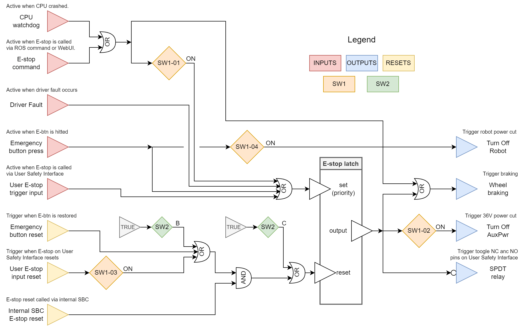
Triggers
CPU Watchdog
The Built-in Computer, which transmits commands and information between the motor controllers and the rest of the system, constantly communicates with the EMU as well. When this communication is interrupted, the EMU will take the following actions:
- Motor drivers will be stopped immediately.
- E-stop will be activated and latched (this feature can be disabled with switch SW1-01).
Built-in Computer E-stop Signal
The process responsible for communicating with the EMU may stop broadcasting on request. It is done by requesting E-stop from:
- ROS:
rosservice call /panther/hardware/e_stop_trigger, - ROS 2:
ros2 service call ~/hardware/e_stop_trigger std_srvs/srv/Trigger.
The WebUI and the Gamepad can call this service, which activates the E-stop.
Switching the physical state of the robot using ROS commands is possible only when SW1-01 is ON.
Driver Fault
The BLDC motor controllers in the robot are high-power devices that have an extensive operation management system. The controller can be programmed to detect sudden spikes in torque, fluctuating control signals, limit current, etc., and send an error signal to the EMU, which will cause activation and latching of the E-stop signal.
Emergency Button Press
Pressing the Emergency Button on the rear robot's panel activates E-stop immediately.
Additionally, another action can be performed, which is to immediately power off the robot if switch SW1-04 is turned ON.
This functionality may be required, but it also has undesirable effects. Remember, you will no longer have control of the robot that loses its power completely before rebooting it, and resetting the E-stop signal will no longer be possible with the Emergency Button, so consider enabling SW1-03 or putting SW2 in the B or C position.
User E-stop Trigger Input
The connector inside the robot can be used to trigger and latch the E-stop signal. Read more about it in the chapter User E-stop Trigger Input.
Resetters
The flowchart explaining the resetting of the robot's E-stop is described in the image below. You will need a maximum of two steps to deactivate the E-stop signal. Note that the order does matter. Both conditions can be modified with switches SW2 and SW1-03.
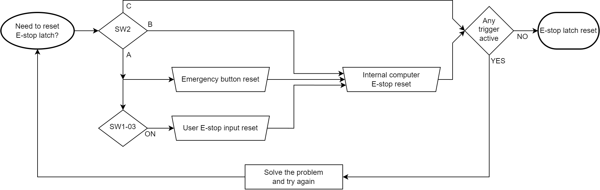
First Condition - Emergency Button Condition
This step is unnecessary by default due to SW2 in the B position.
Chronologically, the first condition to turn off the latched E-stop signal is to reset the Emergency Button on the robot. If the E-stop was triggered in another way than with the Emergency Button, and the Emergency Button is already reset, press it and reset it again.
Alternative to the First Condition - User E-stop Input Reset
This feature is disabled by default due to SW1-03 in the OFF position.
The same function that resets the latch can be performed by the User E-stop input, but only when switch SW1-03 is ON. Switching the User E-stop trigger input on and off will act as a first condition.
Second Condition - Built-in Computer Command
After the first condition is met, or switch SW2 is in position B, the EMU waits for a command to reset the latch. This signal is sent from the Built-in Computer only on request. It can be called from:
- ROS:
rosservice call /panther/hardware/e_stop_reset, - ROS 2:
ros2 service call ~/hardware/e_stop_reset std_srvs/srv/Trigger.
This ROS service is also used by the WebUI and the Gamepad. If the attempt to reset the latch by the Built-in Computer fails, e.g. due to the E-stop trigger signal's presence or failure to meet the first condition, the ROS driver will inform you about it with an appropriate message depending on the attempt channel.
No Conditions - Automatic E-stop Reset
Conditions can be disabled by putting SW2 in the C position. In this case, the EMU will reset the E-stop latch as soon as the problem that caused the E-stop condition has ceased to occur or immediately after releasing the Emergency Button.
Actions
Turn Off Robot
Triggered only by pressing the Emergency Button on the robot, with switch SW1-04 being ON. If you want to use this function on your robot with SW2 in the A position, please consider turning SW1-03 to ON or putting SW2 in the B or C position in order to allow the latch to be reset by other means. Otherwise, the only way to get your robot back up from E-stop is to restart it.
Turn Off AUX Power
The E-stop signal can disable the AUX Power high-voltage power supply. To activate this functionality, turn ON switch SW1-02.
Wheel Braking
Motors will brake the robot when the E-stop signal is activated, the Built-in Computer's CPU crashes or both occur.
SPDT Relay
The User Safety Interface of the robot also contains the relay outputs with the Operating Open and Operating Close terminals, where the operating state is defined when the robot is working properly. Turning off the robot or activating the E-stop signal in the robot switches the relay. Read more about it in the chapter SPDT Relay Output.
EMU Configuration
The EMU is configurable to provide the user with a balance of security and convenience when working on a project using the Panther platform. The following part describes how to set up the EMU responsibly and according to the user's preferences.
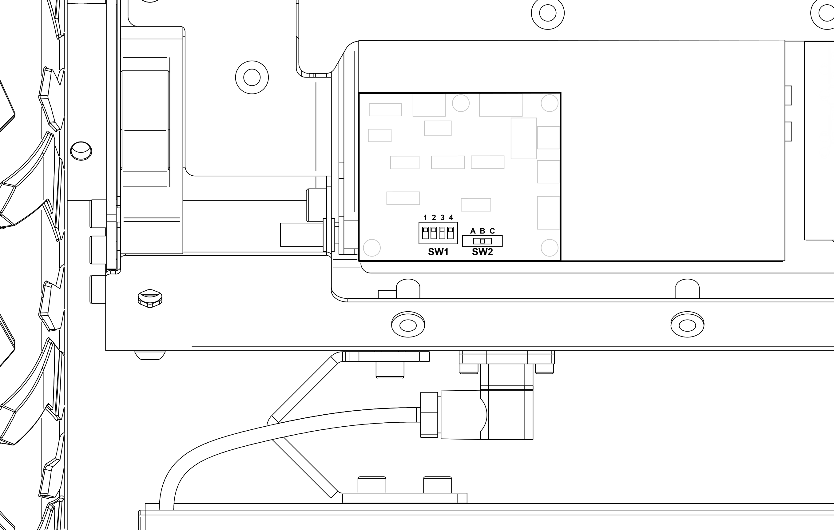
Access to DIP Switches��
To access the EMU configuration switches, remove the rear deck. Read more how to.
On the left side of the uncovered space is placed the Safety Board with two switches on the top surface:
- 4-channel DIP switch named SW1 (poles are numbered from left to right, therefore SW1-02 is the second slider from left on this element).
- 3-position slide switch named SW2 (position A is on the left, B is in the middle and C is on the right side).
Switches at a Glance
SW1 DIP Switch:
| DIP SW | Activated feature | Default |
|---|---|---|
| 01 | activates triggering the E-stop latch due to the Built-in Computer's CPU crash | on |
| 02 | activates AUX power dependency on E-stop | off |
| 03 | activates the User E-stop input as an "Emergency Button condition", usable in SW2-A mode only | off |
| 04 | activates immediately powering off due to an Emergency Button hit | off |
SW2 Slide Switch:
| Position | E-stop latch resetting method | Default |
|---|---|---|
| A | The emergency Button condition and Built-in Computer command are needed to reset the E-stop latch | |
| B | Only the Built-in Computer command is needed to reset the E-stop latch | Default |
| C | E-stop latch resets automatically. The robot can operate just after deactivation of all the triggers, including releasing the Emergency Button - no additional action is needed. This is the least safe config |
User Safety Interface (USI)
The SP1312/S9 socket, accessible from the User Compartment side, is an electrical hardware interface for EMU.

It performs 3 basic functions:
- You can use it to put the robot into the E-stop state.
- You can use it to make other devices mounted on the robot go to the E-stop state at the same time as the robot.
- You can use it to start and stop the robot remotely.
The schematic diagram of the electrical connection is presented in the graphic below.
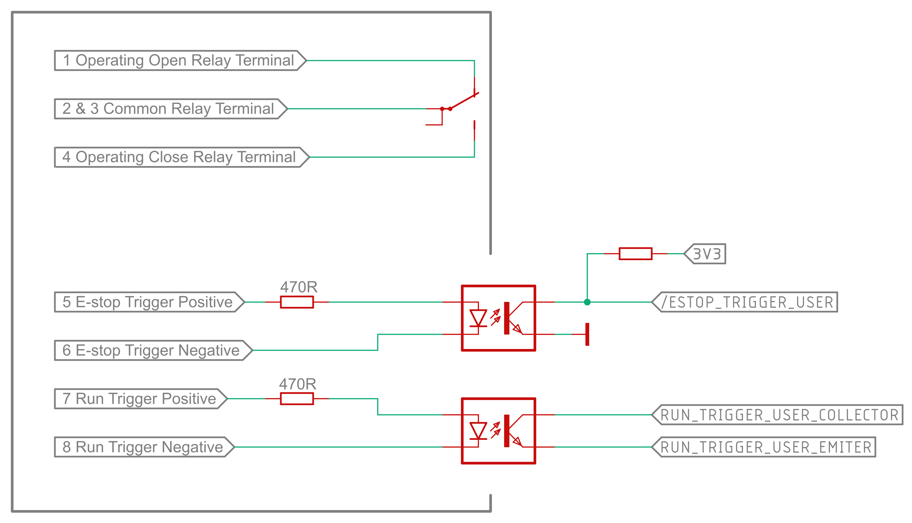
User E-stop Trigger Input
The hardware input is triggered by applying a voltage in the range of 3 V to 12 V to terminals 5 (+) and 6 (-) of the USI connector. It activates and latches the E-stop state on the robot.
SPDT Relay Output
The EMU is equipped with a mechanical contactor that changes its outputs depending on the E-stop state of the robot.
On the connector, it has the form of 4 physical pins, the diagram of which is shown above. The maximum rating for these terminals is 1 A @ 24 V DC / 0.5 A @ 125 V AC.
The table below describes the state of the outputs depending on the state of the robot.
| State | Operating Open | Operating Close |
|---|---|---|
| robot off | connected to common | open |
| robot on, operating normally | open | connected to common |
| robot on, E-stop active | connected to common | open |
Remote On/Off Input
Trigger this input by applying a voltage in the range of 3 V to 12 V to terminals 7 (+) and 8 (-) of the USI connector.
- When the robot is off, applying voltage to this input for 1 second will start the robot.
- When the robot is on, applying voltage to this input for 1 second will start the shutdown procedure.