Manipulators
This subpage contains additional descriptions and manuals about Panther's manipulator modules that are not included in Panther options.
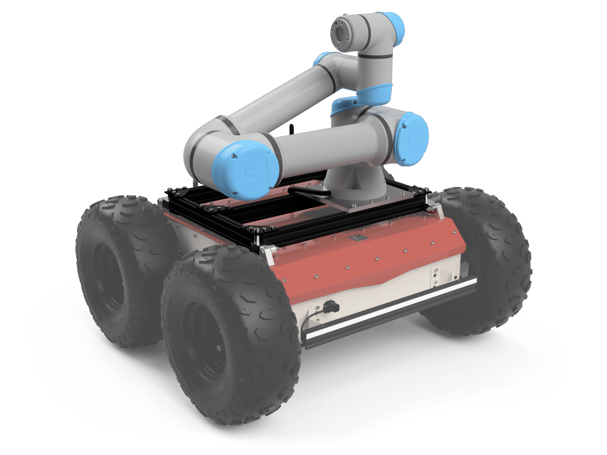
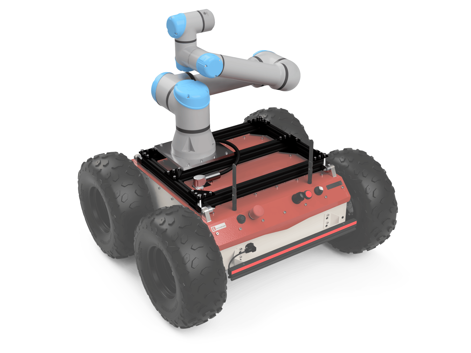
MAN01-02 Universal Robots Cobot
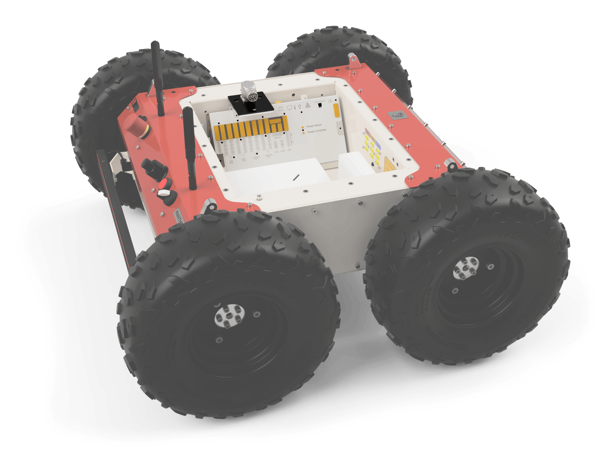
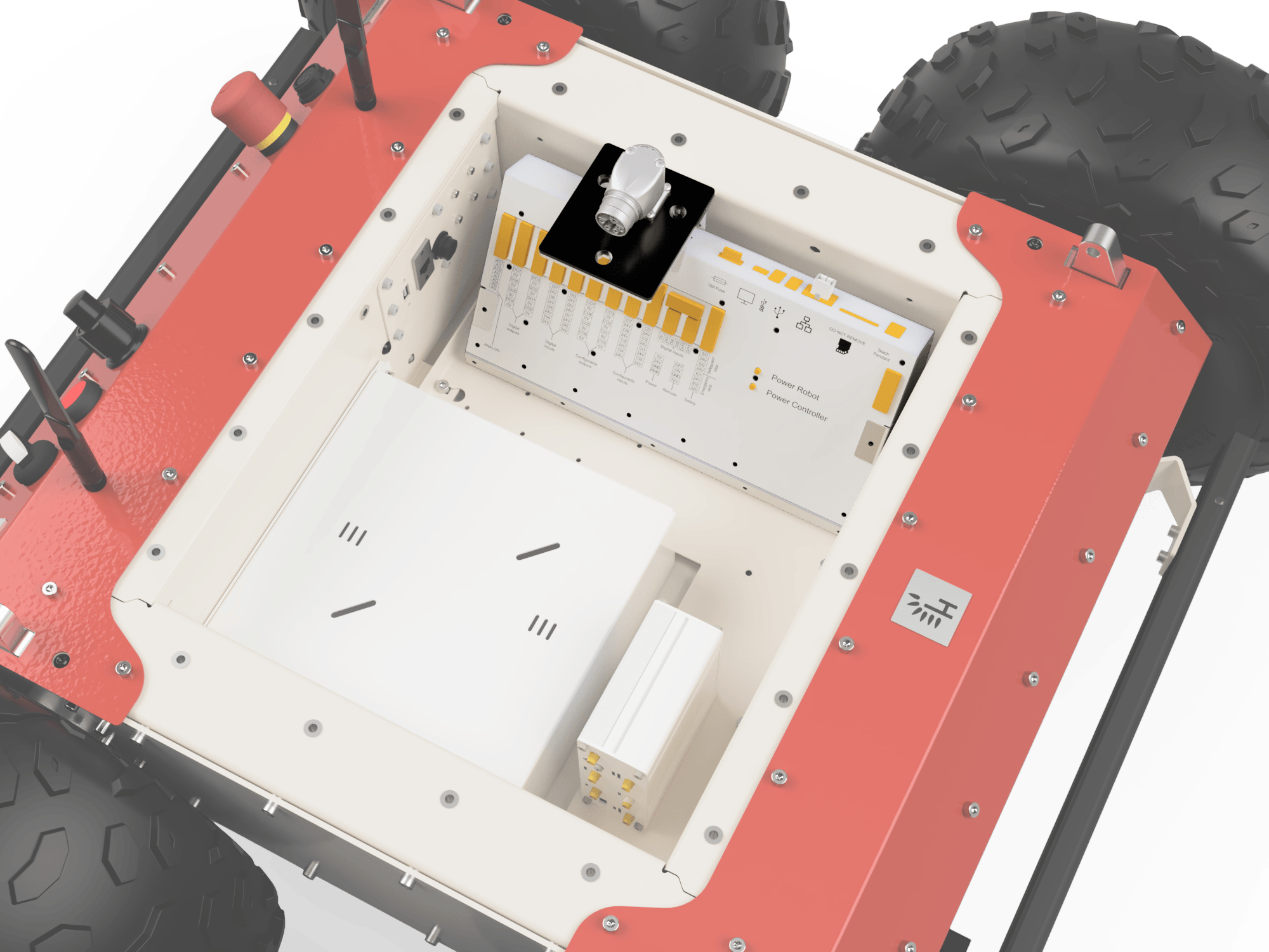
The arm was mounted on reinforced rails of the robot. The arm mounting point is moved forward to increase the reach of the manipulator. The device is connected to the platform with a single cable, the connector of which is located below the railing surface to increase the possibility of mounting other devices and for the safety of the connector itself. The arm controller has been integrated into the interior of the Panther. Some components of the Controller, e.g. the Main Computer, are located in the User Compartment. The Power Converter and Energy Eater have been placed in the side Service Spaces of the Panther.
Instructions found in Panther - quick start are a bit different and do not account for mounting the robot arm. Please follow this guide instead, since it contains additional steps regarding your safety.
This document is an unpacking and assembly instructions for the Husarion Panther + Universal Robots UR5e manipulator.
Precautions
This instruction is intended to be used by personnel qualified to perform simple mechanical assemblies. To assemble the UR5e manipulator on the Husarion Panther robot, we recommend working at least in a team consisting of two workers. This will be mandatory due to large and heavy robot parts that have to be placed and screwed in uneasy conditions.
If any of the steps are not clear to you, contact us at contact@husarion.com
Opening the Boxes
The Panther mobile platform equipped with the UR5e robotic arm comes in two boxes. In the pallet box, there is a Panther platform with sensors, if they were included in the set. The second cardboard box contains a robotic arm and its equipment.
To perform the steps described below, you will need basic tools such as a utility knife and a screwdriver with a PH2 tip, preferably electric. It is a good habit to wear work gloves when handling wooden crates. Ensure at least 3 x 3 m space to operate freely during performing unboxing and assembly.
- Open the door of the wooden chest using the metal locks placed around the perimeter.
- Remove the screws securing the crate sidewalls to the pallet. Remove the walls and lid off the chest.
- Put aside cardboard boxes arranged around the robot. The boxes contain the robot's equipment (like sensors, charger, wires, gamepad).
- The Panther is still strapped to the bottom pallet. Keep it like this during the arm assembly to avoid any movement of the robot.
Some components can be mounted on a wooden base and remain wired to the robot! Be careful not to damage the cable when removing items. Some of them will be screwed to the pallet with screws. The screws must be removed beforehand.
- Open the cardboard box with the robotic arm and remove the polystyrene foam securing the arm to make it ready for assembly on Panther.
Arm Installation
After removing all unnecessary packaging elements, you can proceed to assemble Panther with a manipulator and other sensors. Required tools are 4 mm Allen key, 6 mm Allen key, 10 mm and 13 mm wrenches or hex sockets. Make sure that the wheels are blocked to avoid unintentional driving off the platform and that the battery switch is in the OFF position. Follow the steps below:
- Remove the two M6 DIN 982 M6 self-locking nuts from the shoulder ISO 7379 M6x30 bolts.
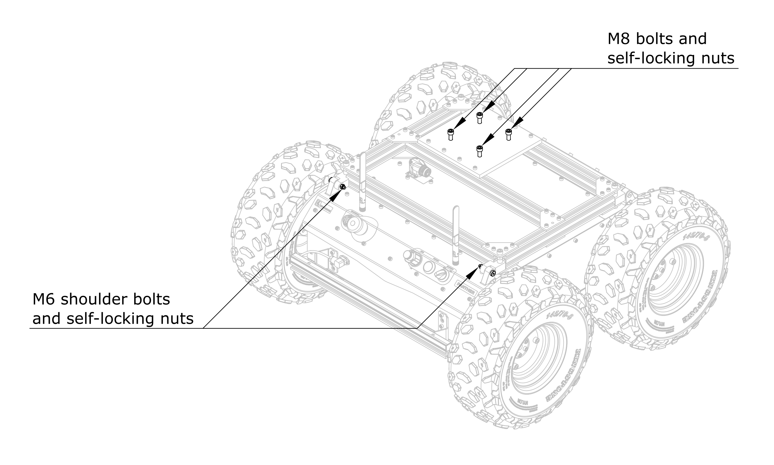
- Tilt the rails forward to the upright position.
If any devices (like sensors) are already assembled to the railings and cables cannot be detached from them, be cautious to avoid any damage to the devices and cables. If necessary, loosen the cable gland and pull the needed cable length out from the gland.
If this is still difficult, you may need to temporarily disassemble these devices from the railings and assemble them back after you finish the manipulator assembly.
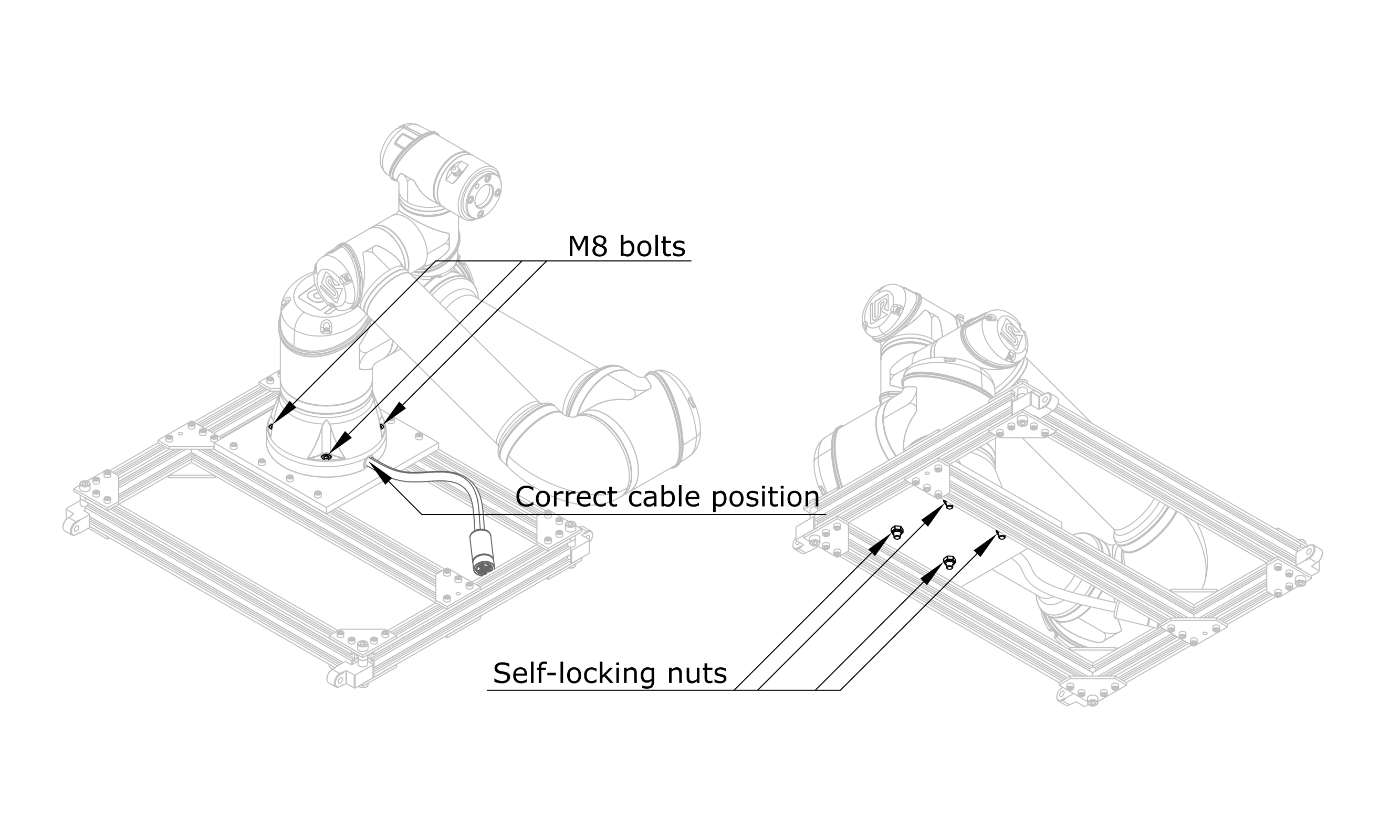
- Remove the four DIN 912 M8x40 M8 bolts and DIN 985 M8 self-locking nuts located loosely in the aluminum mounting plate.
When assembling the mounting rails, please watch out for your fingers which can be pinched, especially with a heavy arm attached to the rails.
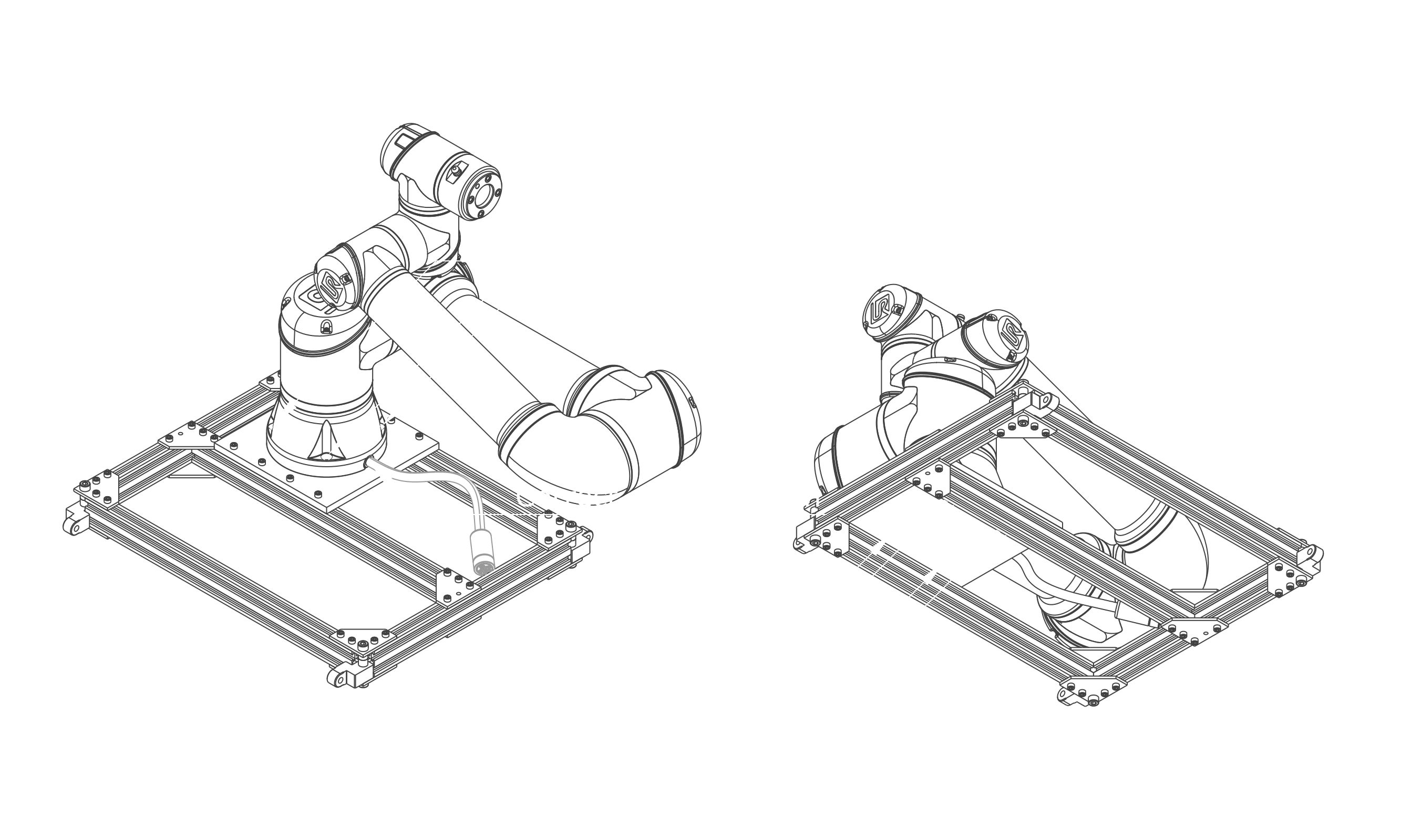
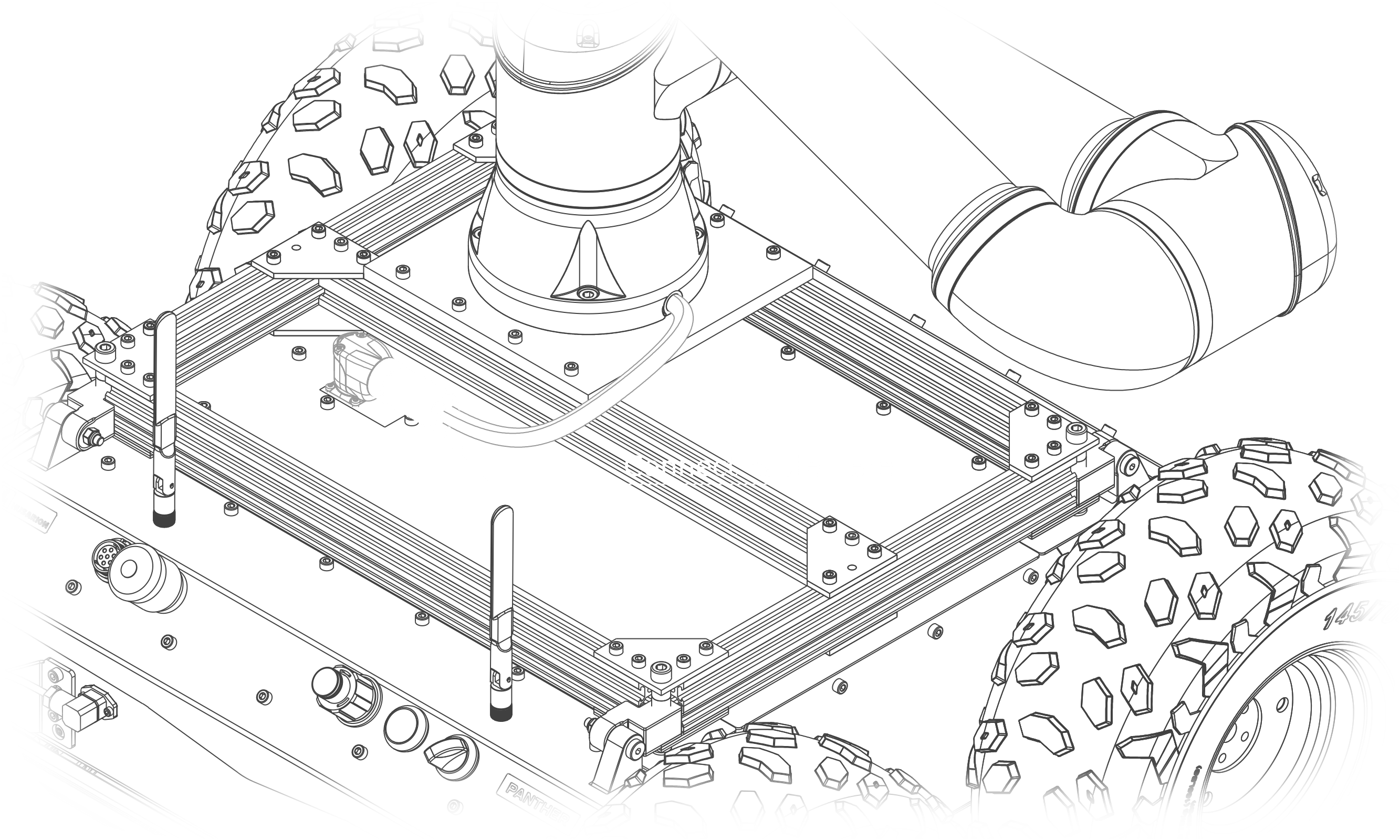
- Secure the robotic arm to the mounting plate using the bolts from the previous step with a torque of 30 - 35 Nm. Pay attention to the direction in which the cable exits from the base of the arm.
- Lower the rails to their original position and fasten them using shoulder bolts and nuts with a torque of 5 - 8 Nm.
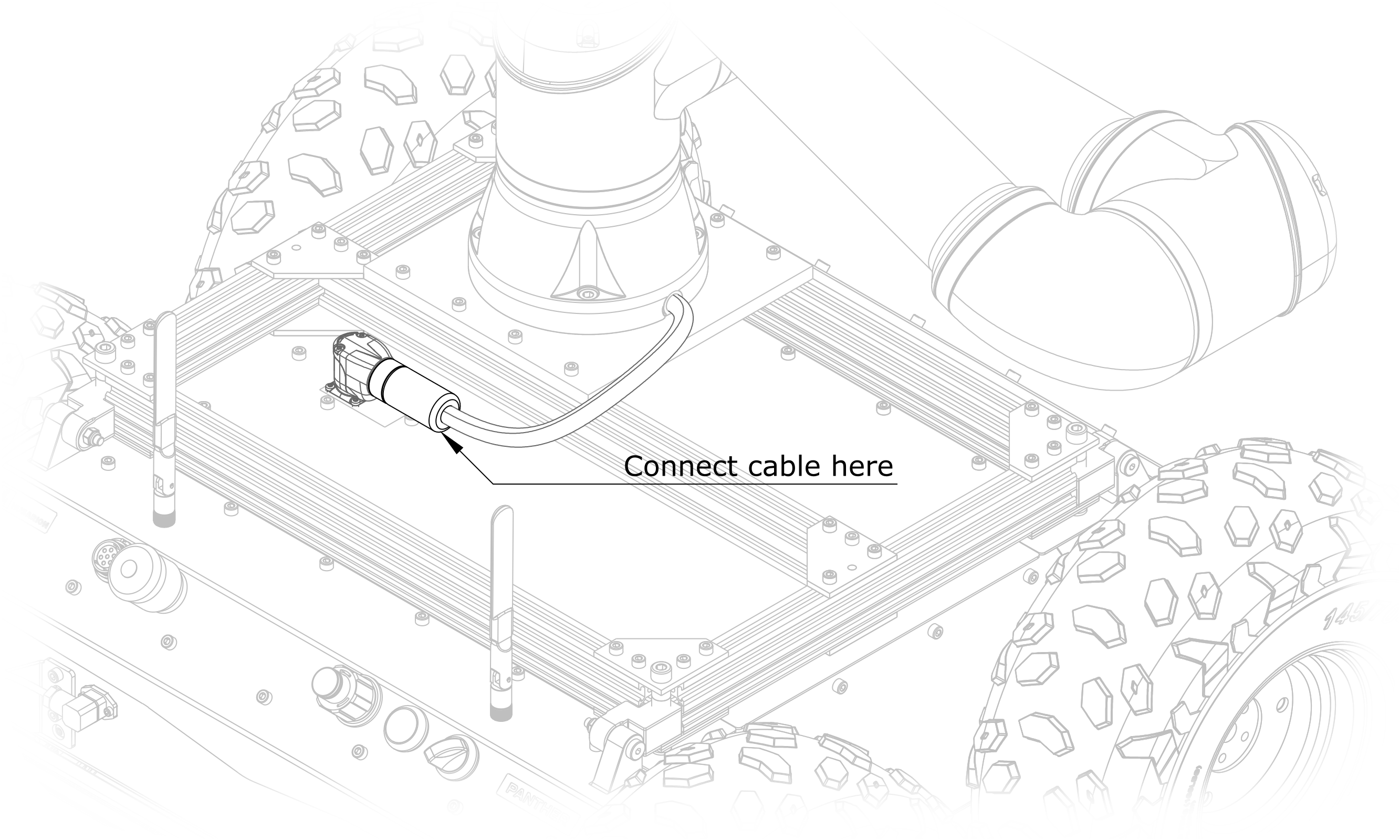
- Connect UR cable to the platform.
If required, attach other sensors and instrumentation to the railings. Cables may require length adjustment on cable glands. Gland nuts should be tightened to ensure the tightness of the connection.
- Cut the straps securing the robot to the pallet.
- Move the robot from the pallet to the floor. The robot can be rolled on wheels. Afterwards, make sure that the wheels are blocked to avoid unintentional driving off the platform.
- Now you can start using the robot.
Software
The necessary information to run the software needed for controlling the UR5e manipulator is available on our GitHub repository.