Panther Manual
Overview
- Panther v1.2
- Panther v1.0 - v1.06
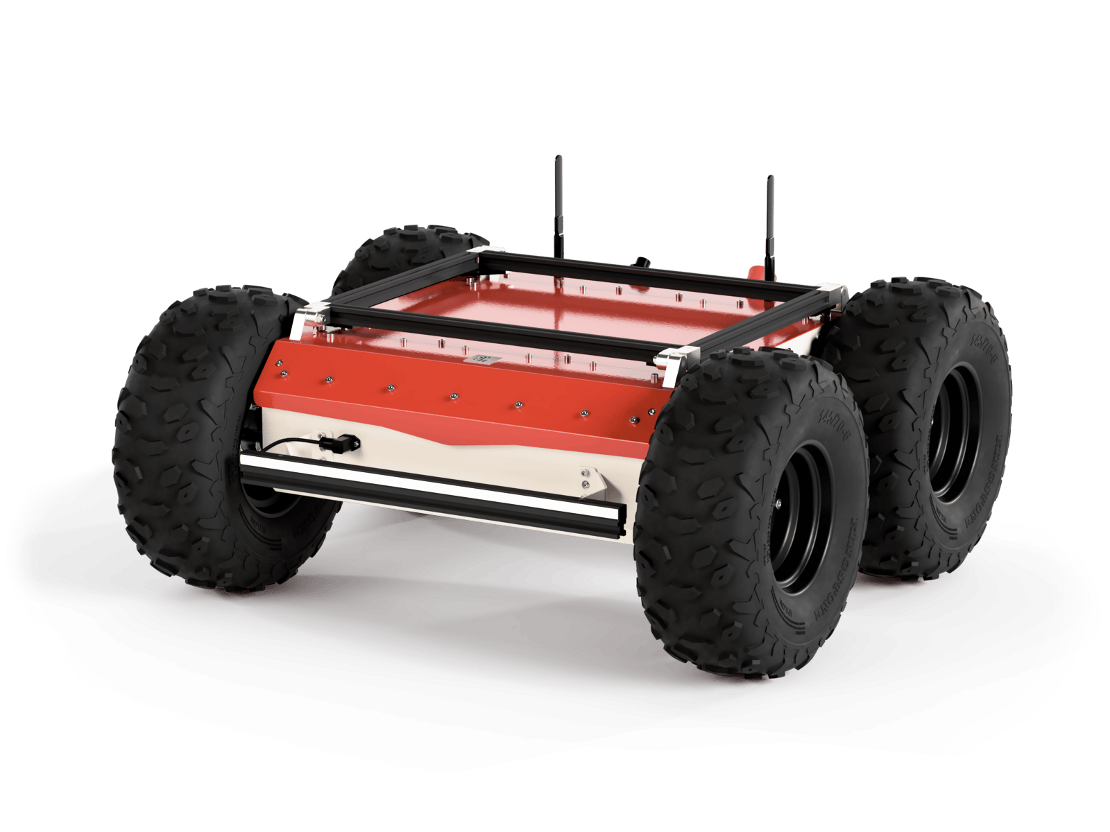

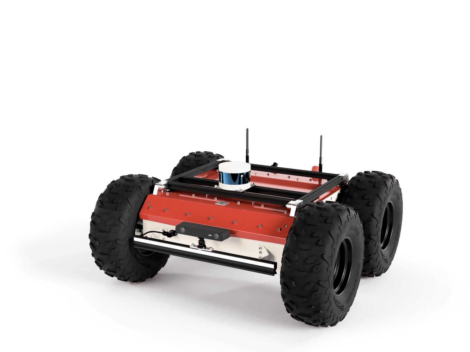
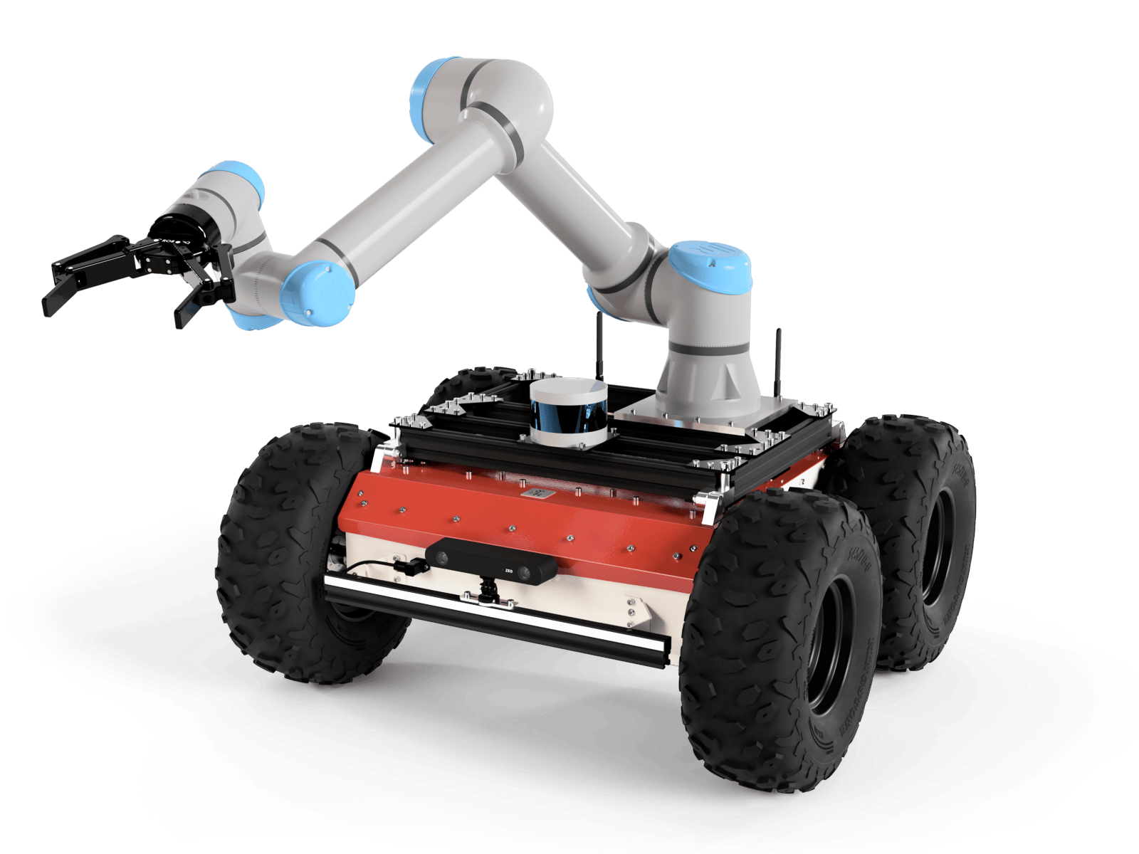
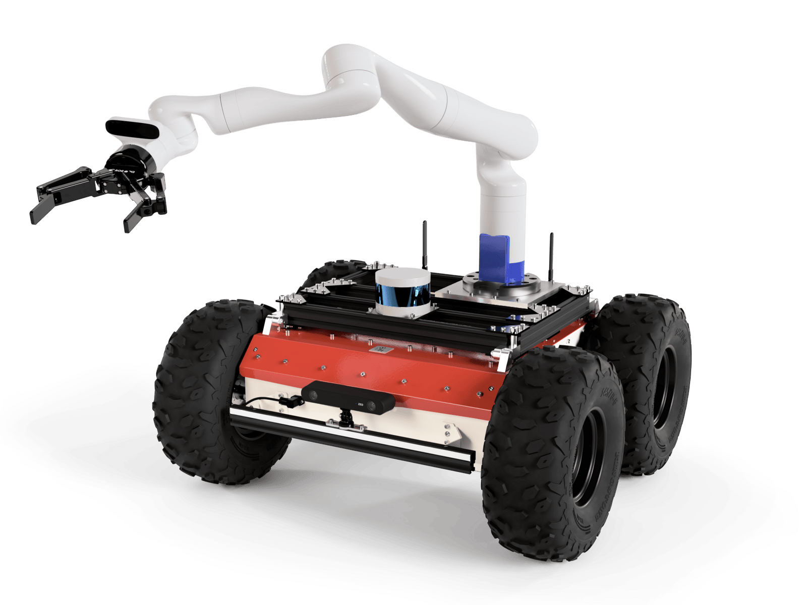
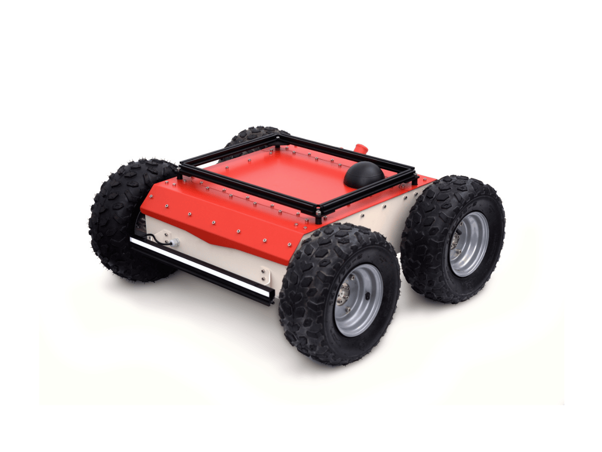
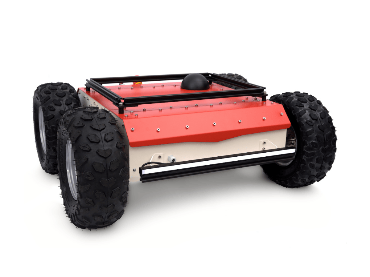
Autonomous, mobile robot (AMR) platform dedicated to an outdoor environment. Compliant with an IP54 or IP66 rate of protection. Depending on the use case, it can be equipped with a robot arm, LIDARs, RGB-D cameras, GNSS receivers, UWB, and other equipment. It can be used in various application areas, such as agriculture, construction, inspection, and many more.
This is a manual. If you need a quick start guide instead, you can find it here.
Before the First Use
We know that you would really like to Quick start with Panther now, but your safety is the most important thing.
Brief Safety Information
- Please read the Safety Instructions first.
- If you are not sure how something works, please read the manual.
- Please remember that the Emergency Button is available on the robot (a mechanical one) and in the software one (accessible from WebUI and Gamepad). Still, in some cases, you may not be able to use them quickly enough to stop the robot before causing damage.
- A detailed description of the safety features is available in the Safety section.
Hardware Guide
Specification
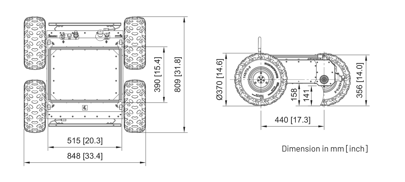
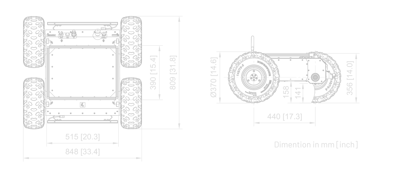
Basic Parameters (with WH01 wheels option and a single Battery)
| Name | Value |
|---|---|
| length | 809 mm |
| platform height | 356 mm |
| overall height | 370 mm |
| wheelbase | 440 mm |
| track of wheels | 695 mm |
| maximum ground clearance | 158 mm |
| minimum ground clearance | 141 mm |
| Name | Value |
|---|---|
| width | 848 mm |
| weight | 55 kg |
| protection index | IP54 / IP66 |
| operating temperature | -20°C to 50°C |
| storage temperature | -20°C to 50°C |
| charging temperature | 0°C to 45°C |
| battery type | Li-Ion 36 V |
Traction Parameters (with WH01 wheels)
| Name | Value |
|---|---|
| max speed | 2 m/s |
| maximum carrying capacity | 100 kg |
| nominal shaft torque | 34.5 Nm |
| maximum shaft torque | 60 Nm |
| nominal total traction force | 725 N |
| maximum total traction force | 1511 N |
| hill grade traversal | 80% (39°) |
| payload (cargo) | hill climb grade |
|---|---|
| 0 kg | 96% (44°) |
| 36 kg | 96% (44°) |
| 52 kg | 96% (44°) |
| 65 kg | 78% (38°) |
| 100 kg | 54% (28°) |
Great traction, large ramp angles, and high stability are ensured by the low center of gravity, located very close to the center of the robot. Details can be found in the files attached in the section Docs and Links.
International Protection Rating
The platform is offered in two variants of the protection class. The basic variant is dedicated to moderate indoor and outdoor conditions, with a rating of IP54. The upgraded variant is dedicated to an extremely demanding work environment with a rating of IP66. Sales details such as price, lead time, and other conditions are available in the store. More details are also in the Panther Options document.
Specification of given ratings:
| Class | Solid | Fluid |
|---|---|---|
| IP54 | dust protected | protection against splashes of water from any direction |
| IP66 | dust-tight | protection against strong water jets (100 l / min) poured on the housing from any side |
Components
| Component | Quantity | Description |
|---|---|---|
| Built-in Computer | 1 | Quad-core 64-bit SoC @ 1.5GHz and 4GB RAM. Used to manage all the basic functions of a mobile platform. |
| User Computer* | 1 | ASUS® NUC (Intel® Core i7-1360P, 16GB RAM, 500GB SSD, GPU: Intel® Iris® Xe), Lenovo ThinkStation P360 Tiny (Intel® Core i7-12700T, 16GB RAM, 512GB SSD, GPU: NVIDIA® T1000), or NVIDIA® Jetson Orin NX (ARM® Cortex® A78AE, 16GB RAM, 512GB SSD, GPU: NVIDIA® Ampere). See Panther Options for details. |
| Router | 1 | Teltonika RUTX11 - Dual-band (2.4 GHz / 5 GHz), Access Point / Client Mode, 4G LTE CAT 6, Bluetooth 4.0 LE, GNSS (GPS, GLONASS, BeiDou, Galileo and QZSS) - This multifunctional device ensures reliable external wireless communication and Ethernet link between internal components of the robot system. More details. |
| Antenna | 2 | Dual-band (2.4 GHz / 5 GHz) placed on the rear of the robot. See all Panther Options. |
| IMU (Inertial Measurement Unit) | 1 | PhidgetSpatial 3/3/3 Precision (3-axis compass, a 3-axis gyroscope, and a 3-axis accelerometer). More details. |
| Front and Rear Bumper Lights | 2 | Signal lighting made of 46 pcs. APA102C LED chips built into an aluminum profile on the robot's bumpers. |
| Brushless Motor with planetary gearbox | 4 | 80PMB800K.80RBL-100 - Drive implemented on 4 durable motors with 473 watts of power (900 W instantaneous power) each and planetary gears (30:1) with a maximum torque of 60 Nm allows the robot to move at a speed of 2 m/s even uphill with a slope of 40% with a load of 50 kg. |
| Encoders | 4 | Quadrature, optical encoder, 400cpr (counts per revolution) mounted on the motor. For one revolution of wheels it will count 30*400 = 12000 counts. |
| Wheel | 4 | WH01 - 370mm standard off-road wheels, WH02 - 203mm mecanum wheels. A recommended tire pressure for WH01 option is 1.0 to 1.5 bar (14 to 22 psi). |
| Additional kits** | Together with the robot, you can get an integrated lidar, depth camera, manipulator, and more. See all at Panther Options. |
By default, there is only up to one User Computer in the robot. For detailed information, see Panther Options.
Most of the external modules are attached to the profiles on the top of the platform. More details.
Communication
Available as standard
- Ethernet
- USB
- Wi-Fi (2.4GHz & 5GHz)
Possible to extend
- LTE / 5G
- GNSS (including GPS)
- GPS RTK (with PC07 or PC09)
- CAN
- RS232
- RS485
See all at Panther Options.
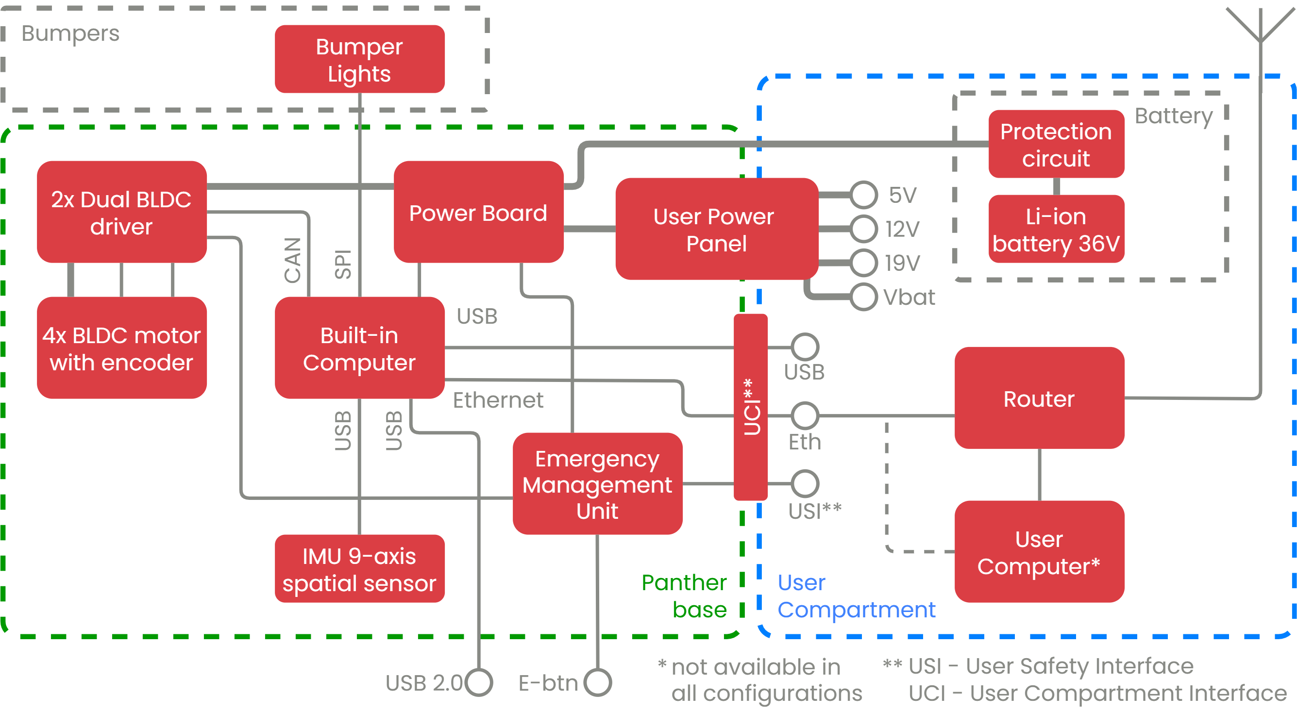
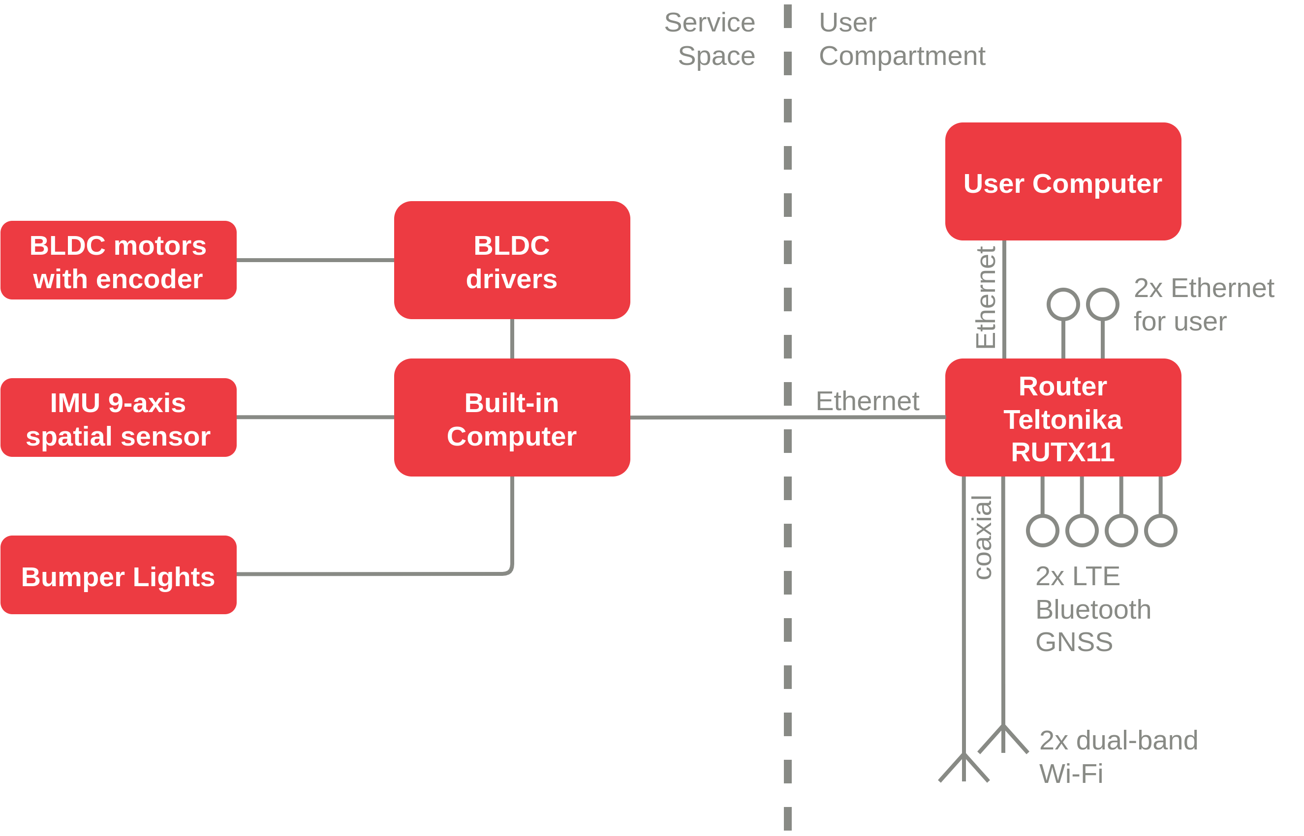
Block Diagram
Graphic representation of Panther components and connections between them. A full, more detailed version of the block diagram can be found in the Docs and Links chapter.
- Panther v1.2
- Panther v1.0 - v1.06
Rear Panel Description
- Panther v1.2
- Panther v1.0 - v1.06
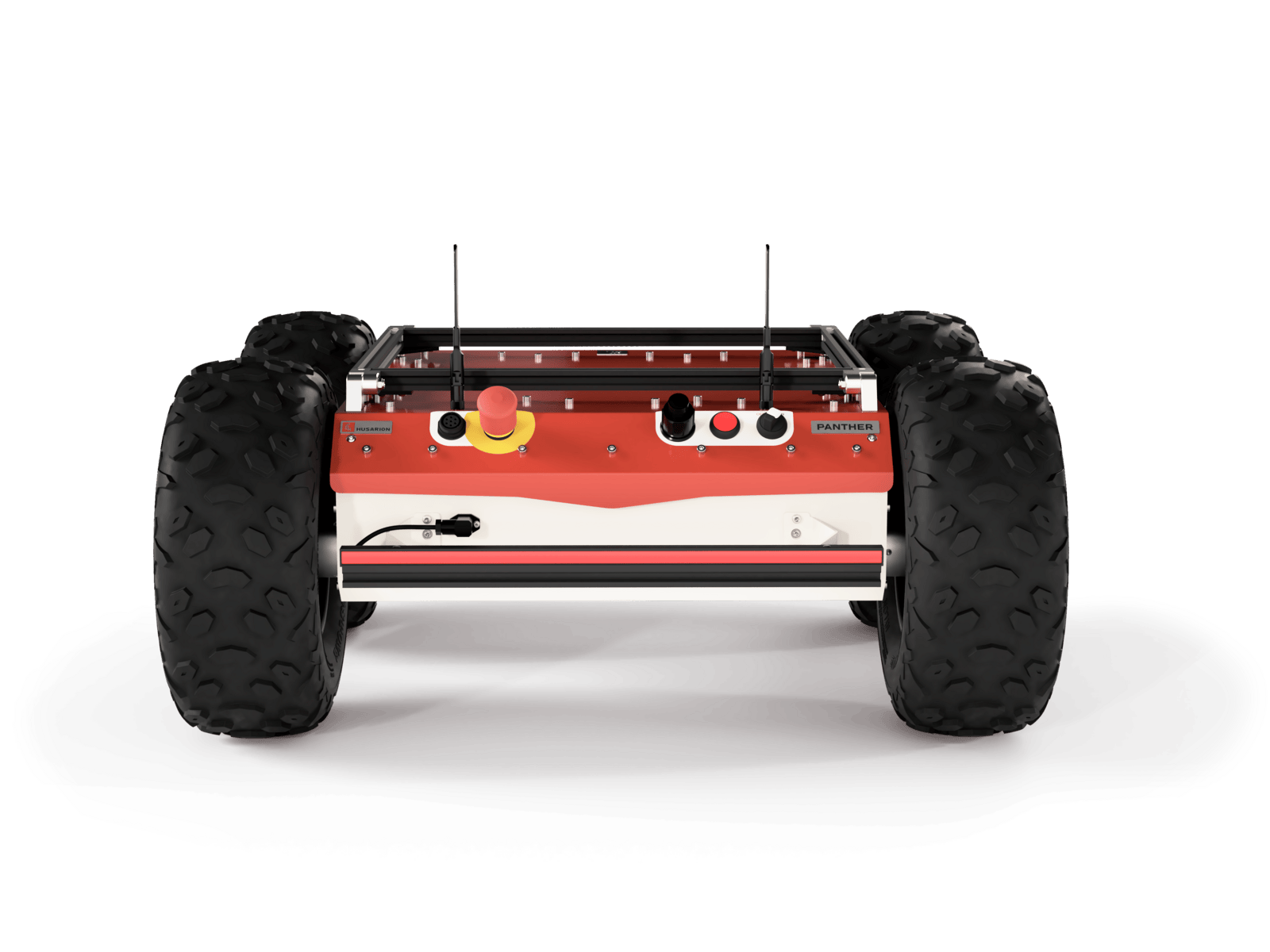
On the Rear Panel of the robot, there are:
- Power controls for the robot - two-position Battery Switch and Power Button.
- USB connection (by default used for Gamepad).
- Emergency Button.
- And the robot's Charging Socket.
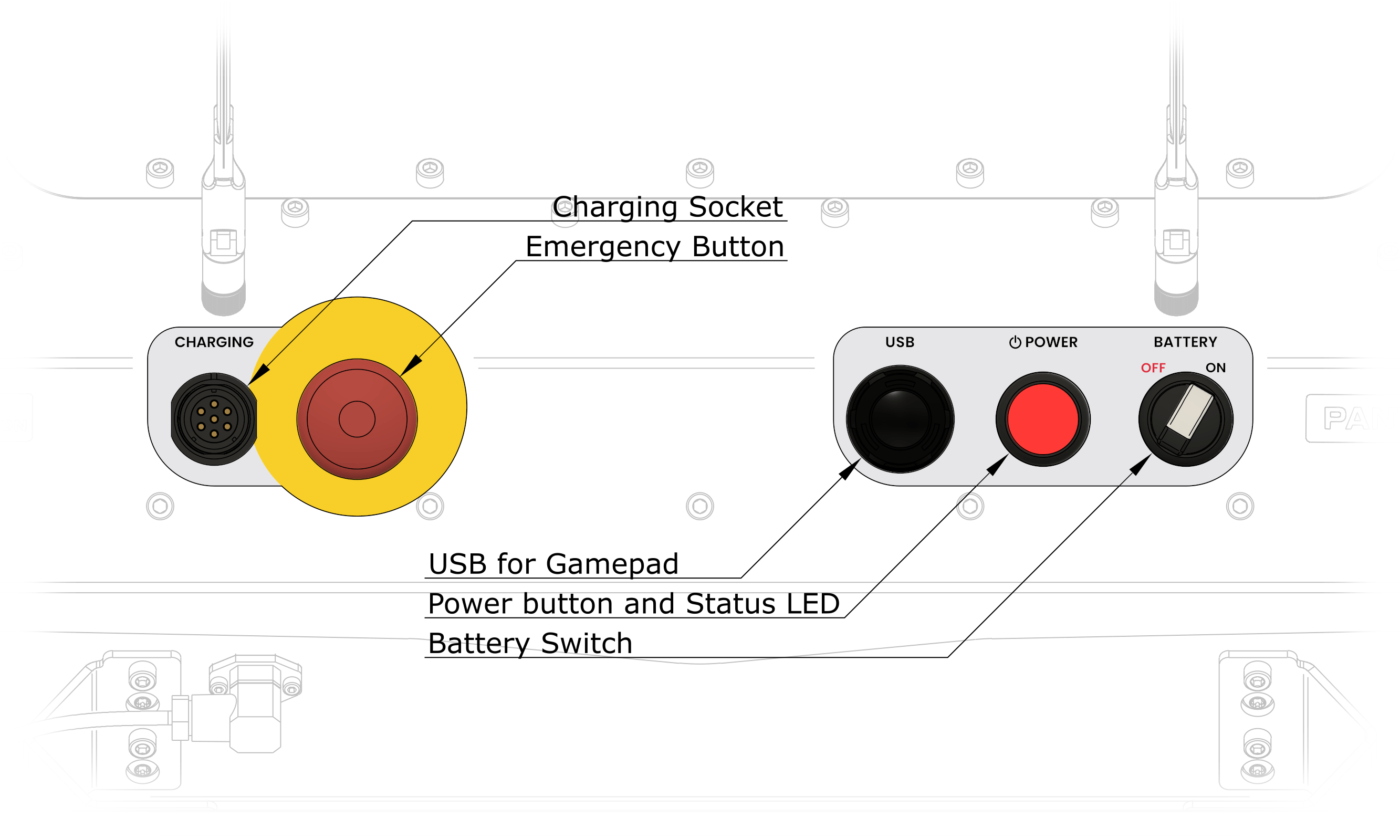
Battery Switch
The Battery Switch is used to cut off the Battery voltage from the robot's electrical circuits. Use this switch for long-time storage and shipping. In the event of a robot malfunction, setting the Battery Switch to the OFF position will turn off the robot immediately, without waiting for the operating system to shutdown.
| Battery Switch position | Knob position | Power state |
|---|---|---|
| OFF | left | battery disconnected |
| ON | right | battery connected |
Cutting off power using the Battery Switch may cause data loss on the Built-in Computer as well as on User Computers.
Cutting off power by putting the Battery Switch in the OFF position is NOT the same as taking out the Battery. When it is necessary to interfere with the internal components of the robot, it is important to remove the Battery from the robot first!
Power Button and Status LED
Power Button action is triggered with a press and hold of the button for 1 second.
| Battery Switch position | Robot status | Power Button action |
|---|---|---|
| OFF | powered OFF | no action |
| ON | powered OFF | power ON |
| ON | powered ON | initialize shutdown |
The Power Button is equipped with an LED that indicates the robot's status:
| LED state | Status of the robot |
|---|---|
| ON | powered on |
| blinking | shutting down |
| OFF | powered off |
When the Power Button is blinking the shutdown process is ongoing. Normally the button should stop blinking after about 10 to 20 seconds. The robot is waiting for the Built-in Computer to indicate a graceful shutdown. In case of an error of Built-in Computer hardware logic will timeout after 140 seconds and cut off the power anyway.
The behavior of the robot after pressing the Power Button can be modified to suit your needs. See Panther Manager for more information.
Emergency Button
The Emergency Button is connected directly to the Emergency Management Unit, and it is one of the inputs triggering the E-stop signal. Pushing it runs several actions on the robot. There is a possibility to program the behavior of the platform in emergency situations, however, the default actions are:
- Activate the E-stop signal and latch it.
- Actively brake the robot using motors.
- Toggle an SPDT relay (external E-stop output).
You can read more about the E-stop in the chapter Safety.
USB for Gamepad
There is an EDAC 690-W04-260-014 connector, which provides a direct USB connection to the Built-in Computer. It is dedicated to connecting the Logitech F710 Pad with a modified waterproof USB receiver, but the port can be used to connect any USB 2.0 device to the computer. Information on how to use the Gamepad with the robot can be found in the chapter Remote Control.
Charging Socket
There is a Weipu SP2112/S7 connector mounted on the Rear Deck of the robot with a waterproof cap. The necessary details on charging can be found in the chapter Charging Panther.
The robot is equipped with a three-position Main Switch and Emergency Button.
| Battery Switch position | Name of position | LED state | Power state |
|---|---|---|---|
| left | Off | Off | turned off |
| center | Stage 1 | On | the robot turned on except the motors |
| right | Stage 2 | On | the robot fully ready for operation |
Pushing the Emergency Button completely cuts off the power to the device.
Cutting off power may cause data loss on the Built-in Computer as well as on User Computers.

Battery & Charging
- Panther v1.2
- Panther v1.0 - v1.06
Battery
The Panther power supply is available with a couple of options for easily swappable battery packs. While purchasing the platform, you can choose the basic 720 Wh Battery (BAT01) or the doubled version of 1440 Wh (BAT02). Read more about it in the section Panther Options.
The Battery packs are made of Lithium-Ion cells with a rated voltage of 36 V and 20 Ah or 40 Ah capacity, which gives the Panther enough energy to move around in demanding terrain and perform calculations for about 3.5 hours in the standard version and 7 hours in the doubled version. Moving the robot in friendly terrain allows for a significant extension of the robot's working time, up to 8 hours (standby time up to 40 hours) for the single Battery variant. You can check more specific information about Panther power consumption calculated for the basic version of the Battery.
You can check the battery charge level via the /panther/battery/battery_status topic, the WebUI, or by observing the battery charge on Bumper Lights during charging. During normal operation, when the battery level is low (below 40% or 36 volts) or very low (below 10% or 33 volts), the animation will periodically display an orange or red indicator. You can find a preview of the animation in the section dedicated to Animations.
For more information about the Bumper Lights, please see the LED Animations and Bumper Lights sections, respectively.
| Battery parameter | Value for BAT01 | Value for BAT02 |
|---|---|---|
| battery capacity | 720 Wh | 1440 Wh |
| runtime | 3.5 h - 8 h | 7 h - 16 h |
| standby time | 40 h | 80 h |
| total output power | 1.0 kW | 2.0 kW |
| maximum peak power | 1.8 kW | 3.2 kW |
Using WCH01 (and WCH02) Wireless Charger option, the robot can charge autonomously in the docking station. See the dedicated page: WiBotic Wireless Charger WCH01/02
Battery Swap
To remove, insert, or replace the Battery, you require access to the User Compartment. You will learn how to do it in the chapter User Compartment.
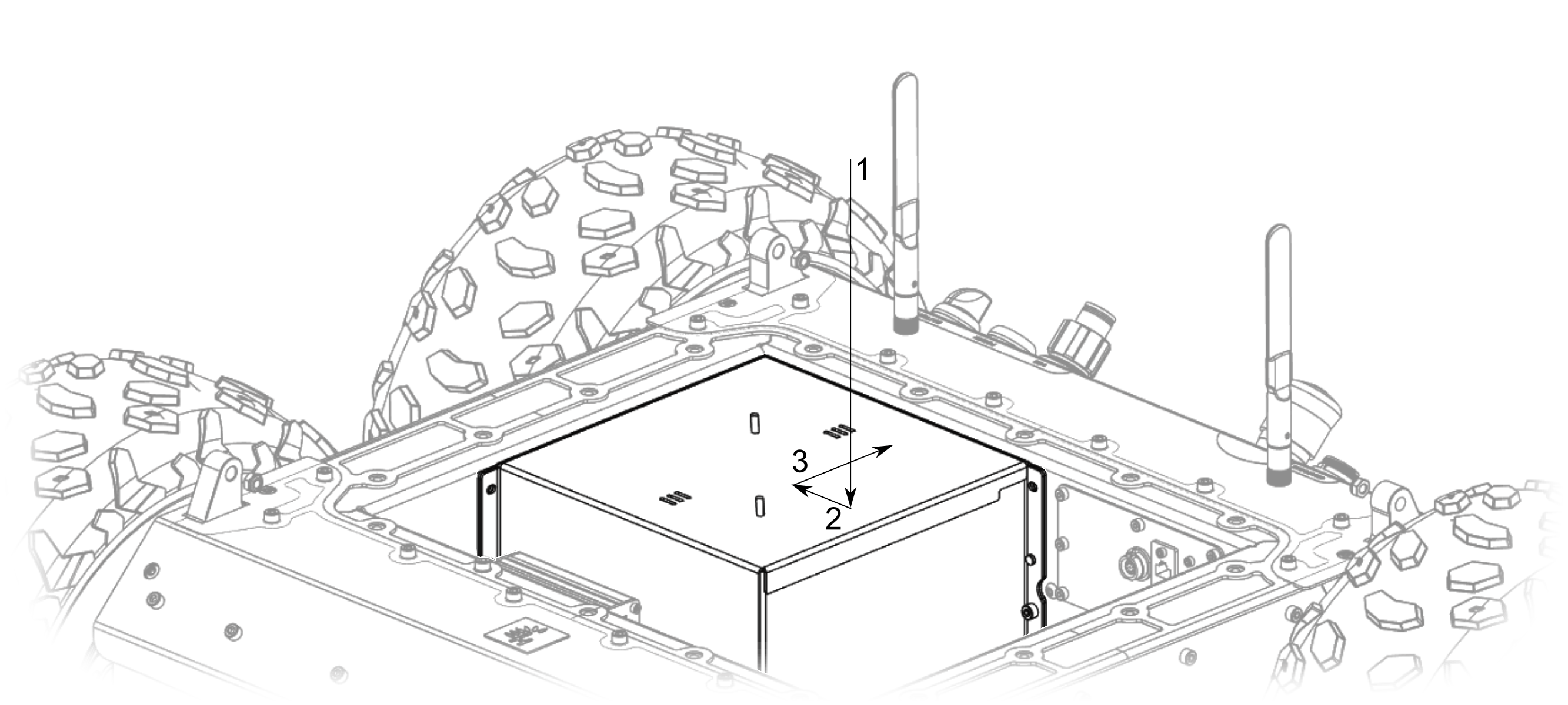
The Battery is attached to the inner walls of the robot with DIN 912 M5x12 bolts (4 mm Allen key). After removing the bolts (2 pcs for BAT01 and 4 pcs for BAT02) holding the Battery in place, slide the Battery out of the electrical connector by sliding the package towards the front of the robot by approximately 10 mm. After that, the Battery can be lifted by the handle located on its upper surface.
There are retaining pins pointing out of the Battery, be careful not to damage the seal on the surface of the robot. The Battery is heavy and can damage electronics and wires placed on the User Shelf if not lowered carefully. After lowering (1) the Battery to the bottom of the User Compartment, slide it towards the right side (2) of the robot and then along this wall to the rear (3) of the robot. The locating pins should finally position the Battery, which will slide smoothly into the power socket. The bolts holding the Battery in place should be tightened to a torque of 4 Nm. The steps described above are marked in the figure below.
Battery
The Panther is equipped with a Battery made out of cells in Lithium-Ion technology with a rated voltage of 36 V and 20 Ah, which gives it 720 Wh of energy to use for calculations and move around in demanding terrain for about 3.5 hours. Moving the robot in friendly terrain allows for a significant extension of the robot's working time, up to 8 hours (standby time up to 40 hours). You can check for more specific information about Panther power consumption here.
When the Battery level is low, the Bumper Lights display this status through two distinct animations that are shown periodically. If the Battery level drops below 40% (36 volts), the Bumper Lights will display an animation of two orange stripes moving toward the center. If the Battery level drops below 10% (33 volts), an animation consisting of two red stripes moving towards the center is displayed.
For more information about the Bumper Lights, refer to the Bumper Lights section.
To meet the user's needs, the robot is equipped with 9 high-power electrical connectors that are able to provide a total of 360 W of power to the user's devices. The supply voltages available on the User Power Panel are 5 V with a total current limitation of up to 15 A (3x female XT60), 12 V limited to 20 A (3x female XT60), and 19 V limited to 10 A (3x female XT60).
The layout of the connectors can be found in the chapter User Compartment.
One of the 19 V outputs is used by the User Computer and one of the 12 V outputs is used by the Router.
| Battery parameter | Value |
|---|---|
| battery capacity | 720 Wh |
| runtime | 3.5 h - 8 h |
| standby time | 40 h |
| total output power | 1 kW |
| maximum peak power | 1.8 kW |
| max power for user use* | 5 V @ 15 A, 12 V @ 20 A, 19 V @ 10 A |
| total power for user use* | 360 W |
Each of the voltage sources has an independent overcurrent switch, but the total power consumed by the devices plugged into the User Power Panel cannot exceed 360 W.
Charging Panther
- Panther v1.2
- Panther v1.0 - v1.06
In the set with the robot, we provide a dedicated Charger, which can charge the robot to 80% in 4 hours, and to 100% in 7 hours. The dedicated Charger can be connected directly to the robot's Charging Socket on its housing. There are two types of chargers available. By standard, Panther is shipped with a wired Charger - single or dual (in case of BAT02 option). On the top of these Chargers, there are LED indicators. If all of them are green, that means the Battery is fully charged or not connected. When at least one LED is red, that means the Battery is charging.
Another type of charger is a wireless charger. You can read more about it in the Panther Options section. The wireless charger has also a separate page in manual: Wireless charger.
The charging time for the double Battery (BAT02) should be very close to the single Battery (BAT01). This is possible due to the dedicated Dual Charger for BAT02.
| Parameter name | Single Charger | Wireless Charger | Dual Charger |
|---|---|---|---|
| suitable battery options | BAT01 | BAT01 | BAT02* |
| input voltage range | 100 - 240 V AC | 100 - 240 V AC | 100 - 240 V AC |
| input voltage frequency | 50 - 60 Hz | 50 - 60 Hz | 50 - 60 Hz |
| max output voltage | 42 V | 42 V | 42 V at two channels |
| max output current | 5 A | 5 A | 2x 5 A |
* - The dual Charger can also charge the robot with BAT01.
It is forbidden to drive the robot during the charging process!
When you do not plan to use the robot for the period longer than 4 weeks, please make sure that the battery level is at least 40...50 % to avoid Battery degradation due to self-discharge. For even longer periods, check the battery level every 3 months and keep above 30 % (35 V).
In the set with the robot, we provide a dedicated 42 V @ 5 A Charger, which the robot will charge to 80% in 4 hours and to 100% in 7 hours. The mains-operated Charger is connected directly to the robot's Charging Socket on its housing.
It is highly recommended not to use the robot during the charging process!
Please do not leave the Charger connected to the robot after the charging process is completed (the red LED and the Charger fan will turn off).
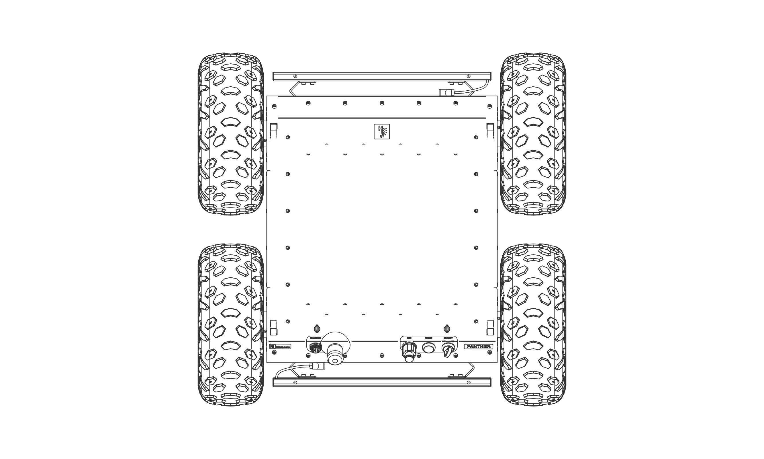
Mounting Rails
Sensors, equipment, and payloads can be attached to the profiles on top of the robot. The profiles used are aluminum V-slot 2020 profiles. The best way to attach the elements to them is to use mounting elements dedicated to this type of profile, such as T-nuts, fittings, and angles.
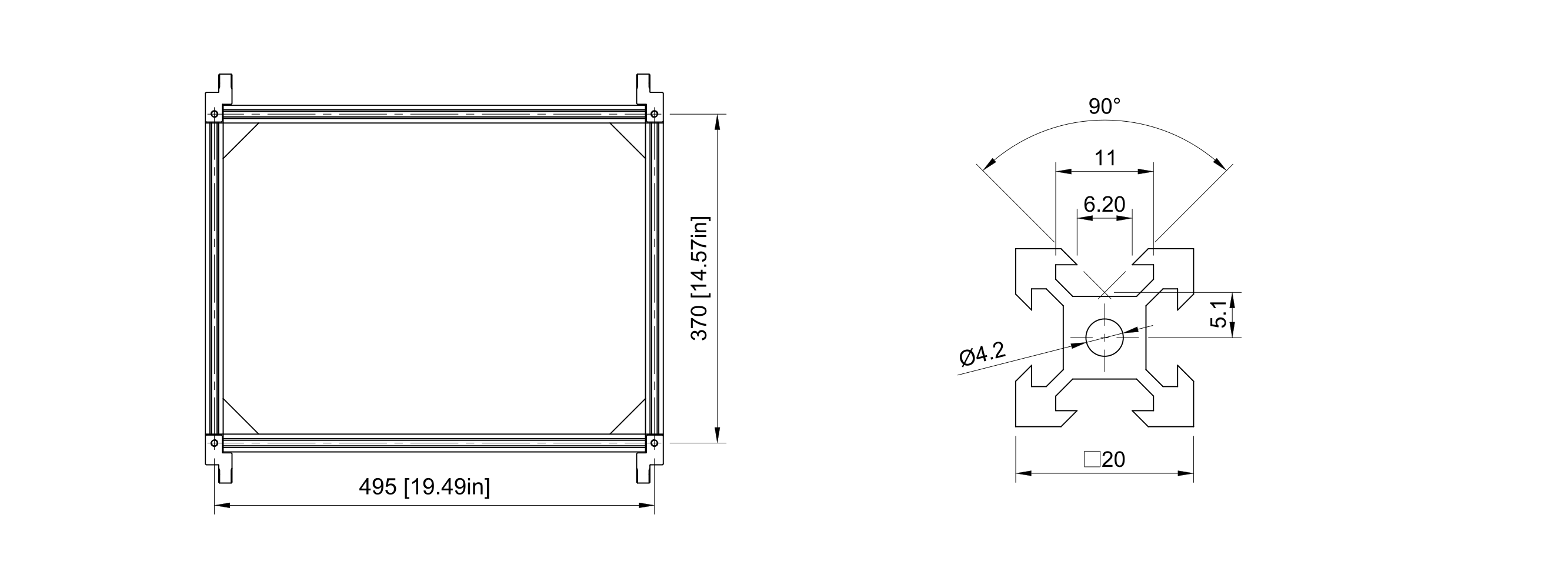
These profiles are fixed to the robot with four ISO 7379 M6x30 shoulder screws with DIN 986 M6 nyloc nuts.
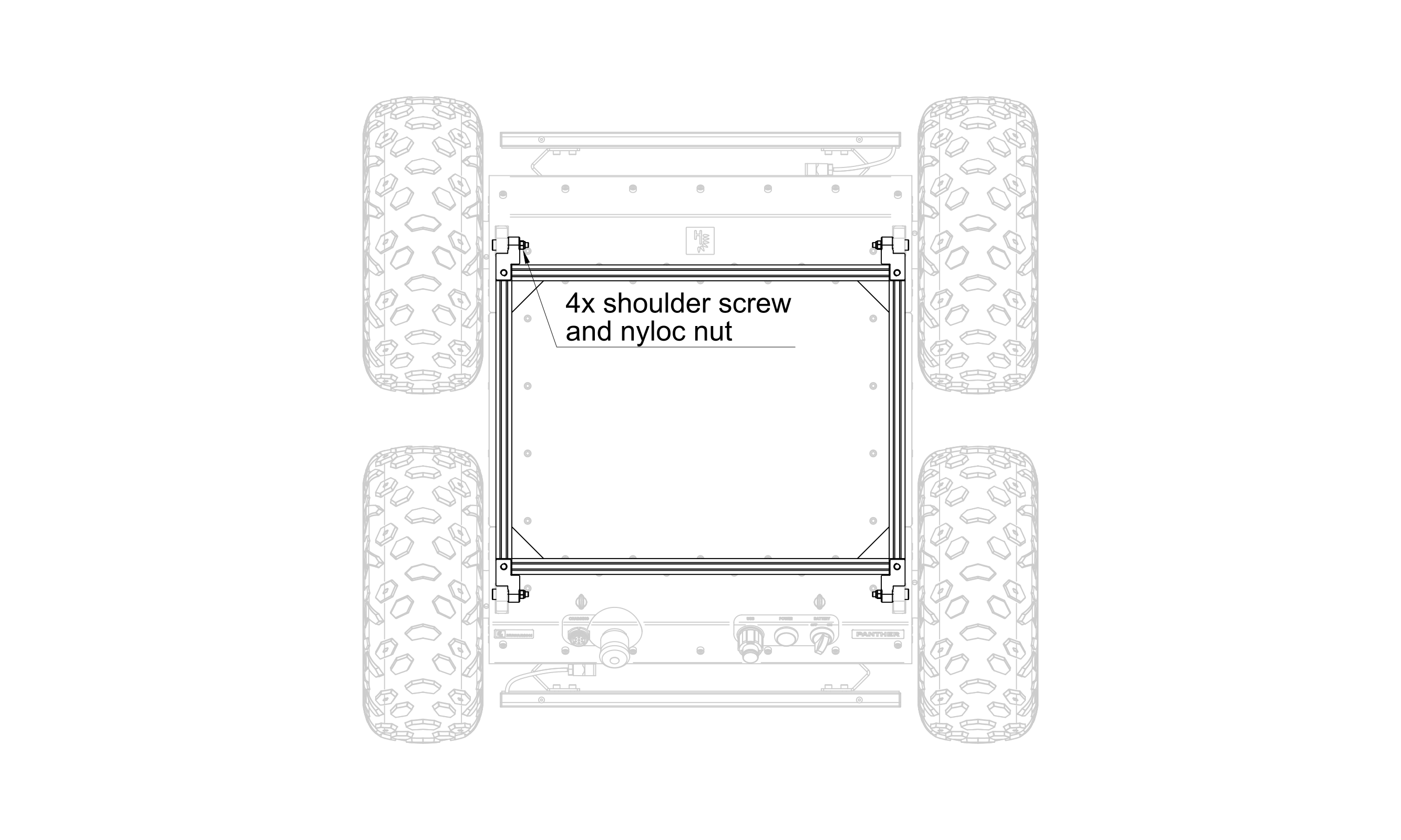
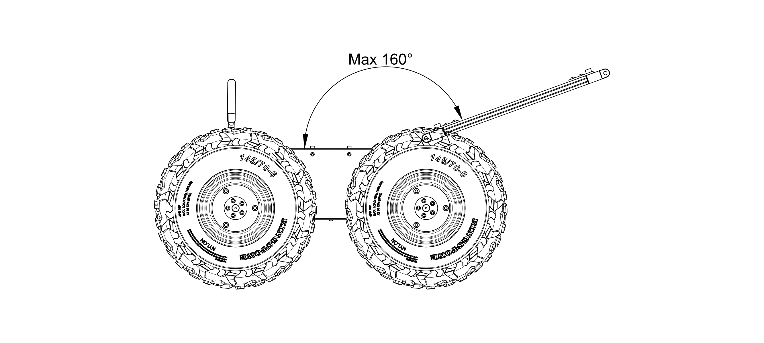
To enable access to the User Compartment, top rails can be pivoted by removing 2x shoulder screw M6x30 and 2x DIN 986 M6 nyloc nut in either the front or back. The maximum opening angle is 160 degrees with the built-in stop.
For more useful information in the field of mechanics, please see the document Panther Overall Dimensions and the chapter CAD models.
The presence of the Mounting Rails has no effect on the water and dust resistance of the robot.
Bumper Lights
The robot's Bumpers are made of a profile with the same cross-section as the Mounting Rails. They are 0.5 meters wide, and, in addition to buffering shock and reducing potential damage when the robot collides with an obstacle at high speed, sensors can be mounted to them. By default, the signaling lighting is mounted on each Bumper in the form of aluminum profiles with 46 programmable RGB LEDs.
These lights may be widely used to indicate the status of the robot, the direction of movement or the intention to change direction, warn about low Battery charge or other detected errors, signal the status of the charging process, or even to illuminate the area in front of the robot. More details regarding Bumper Lights and their control are available in the section LED Animations.
User Compartment
- Panther v1.2
- Panther v1.0 - v1.06
The robot's volume has been divided into five parts. The central space, called the User Compartment, is dedicated to the user's components and electronics. The User Computer (for example, PC02 from Panther Options), the RUTX11 router, as well as the robot's Battery are located there.
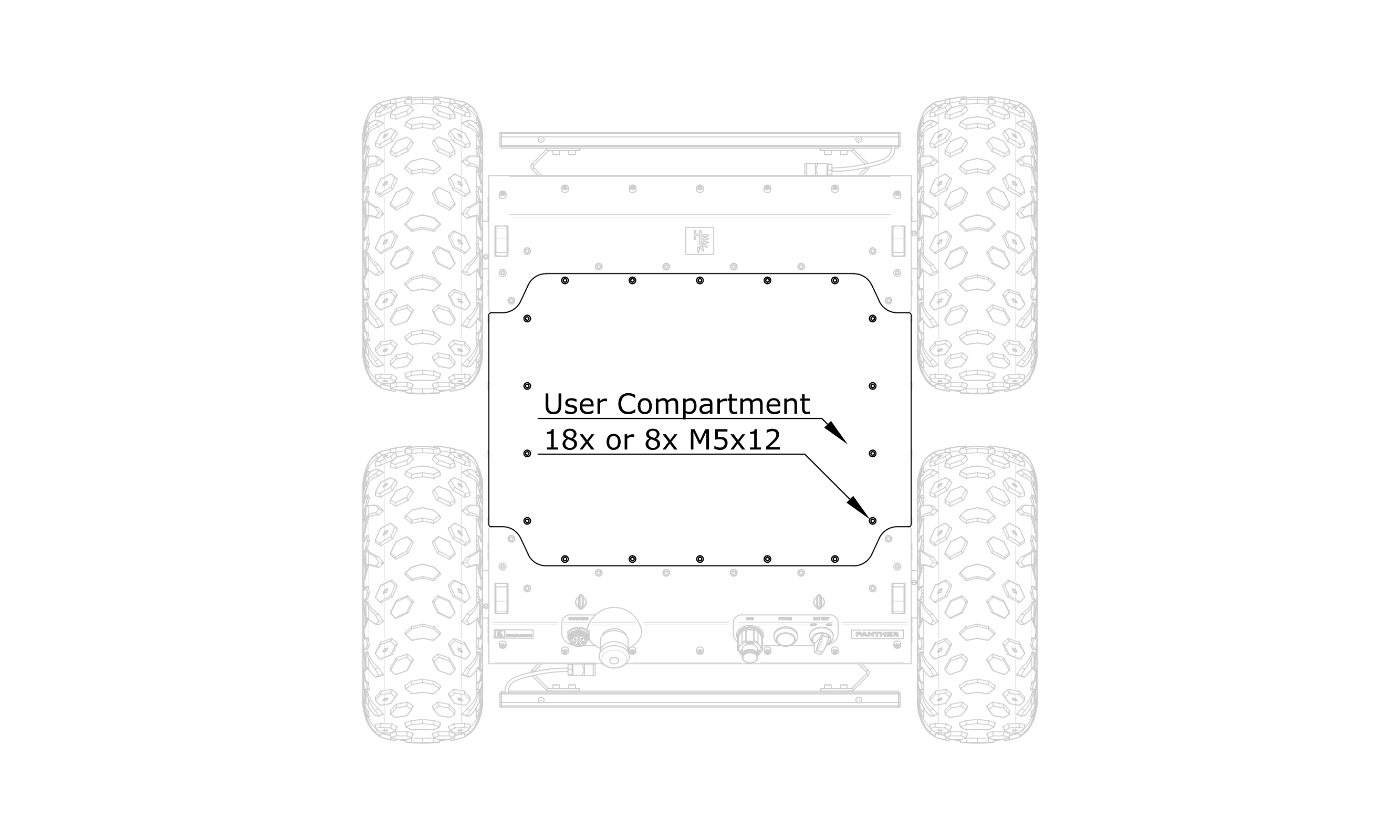
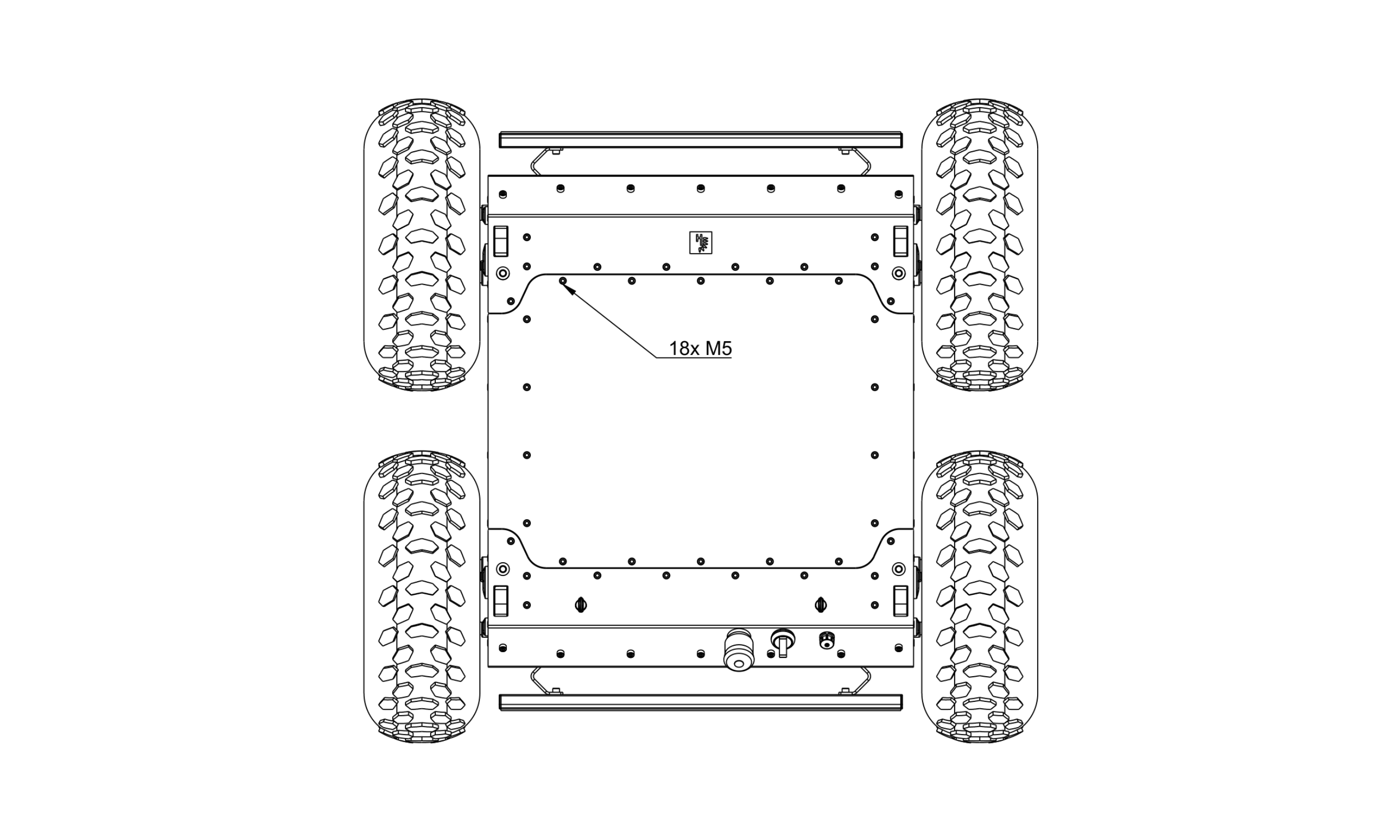
Access to the User Compartment
To access the User Compartment, pivot the Mounting Rails by removing 2x ISO 7379 M6x30 shoulder screws with DIN 986 M6 nyloc nuts. Then unscrew the Cover fastened with 8x (IP54) or 18x (IP66) bolts DIN912 M5x12.
To ensure the tightness of the robot, make sure that there are no foreign objects on the seal when assembling the skin element and tighten the bolts with a torque of 4 - 5 Nm.
User Shelf
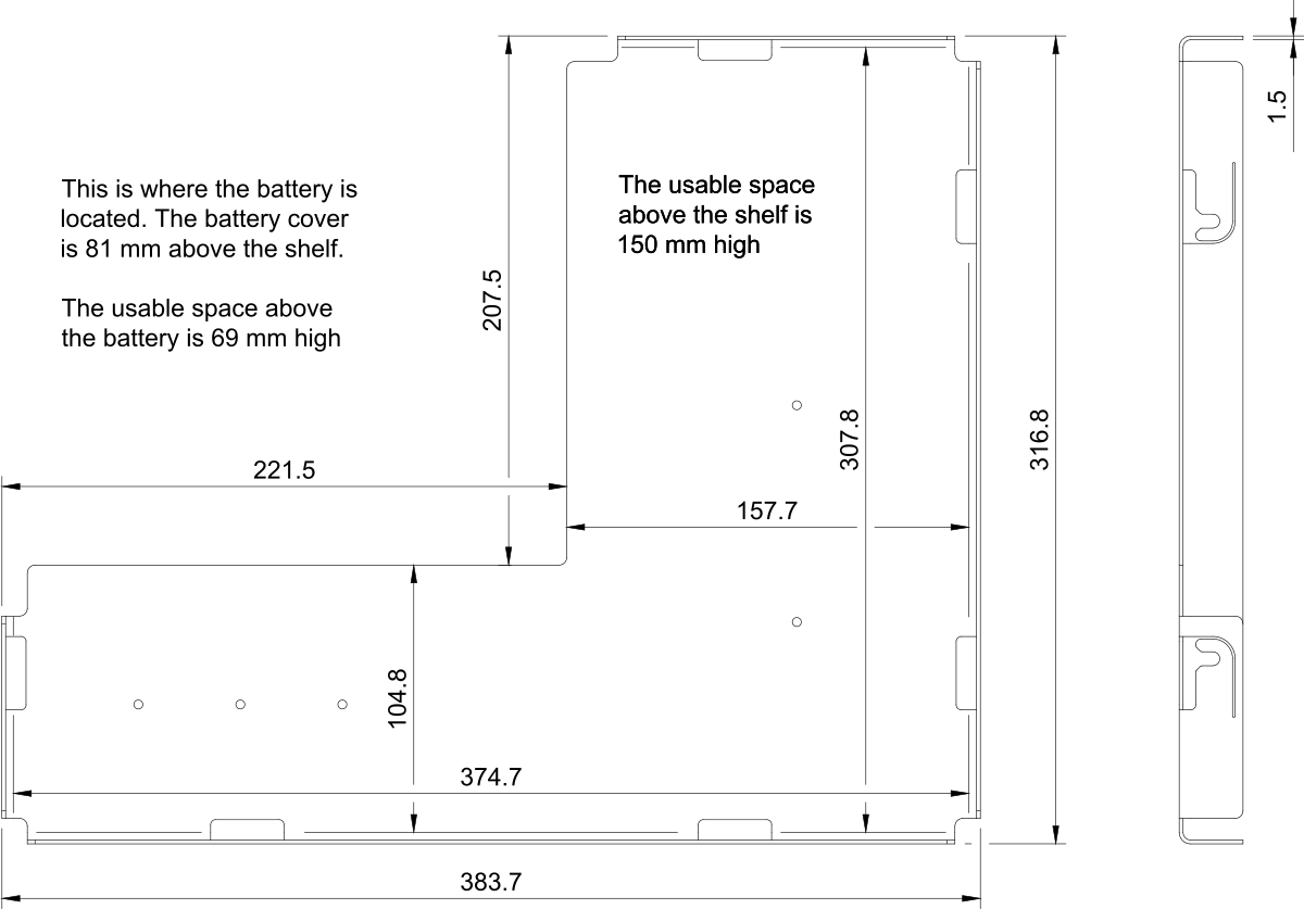
The volume of the User Compartment is approximately 13.6 liters (3.6 US gallons) with the BAT01 option or 10.0 liters (2.6 US gallons) with the BAT02 option. This part of the robot has the same water and dust tightness class as the robot. At the bottom of this volume is an easily removable User Shelf to which devices located in this space are attached, excluding the Battery.
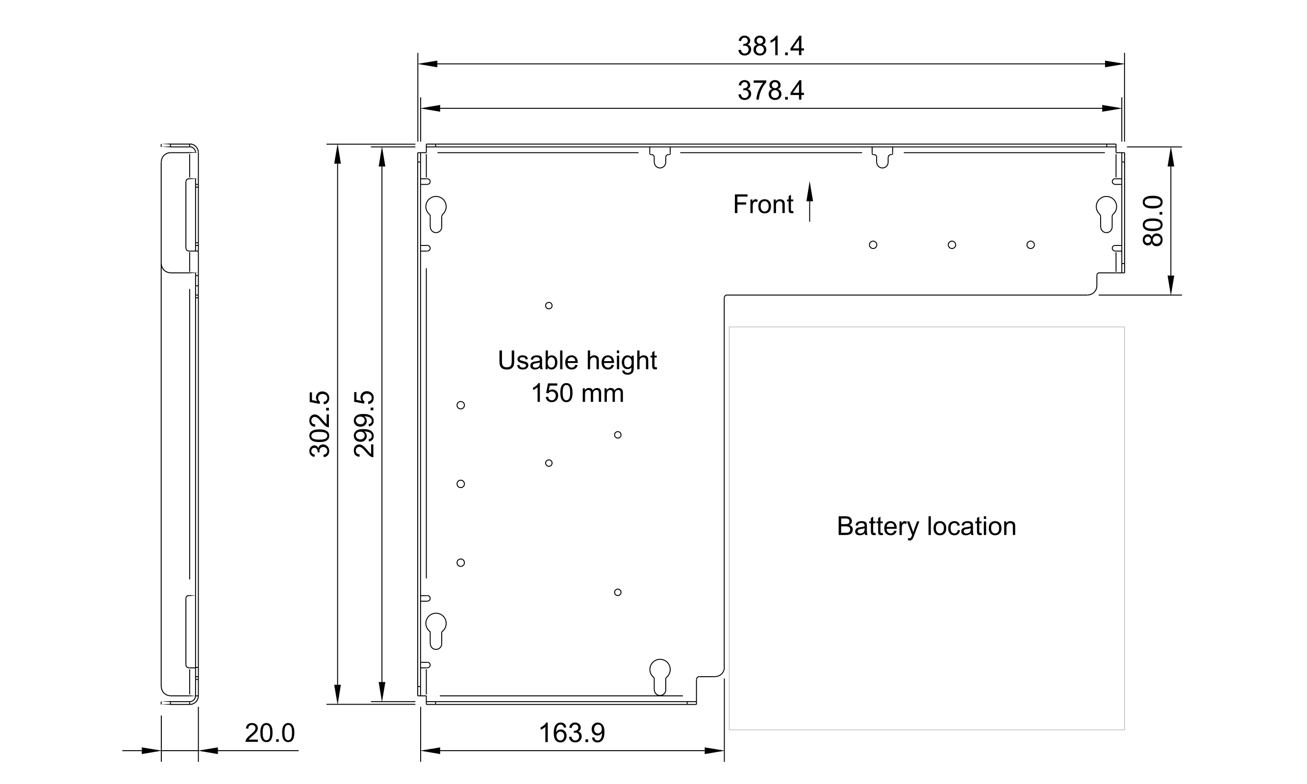
The usable space above the User Shelf is 150 mm high. The top surface of the BAT01 Battery module is 72.5 mm above the User Shelf. The usable space above this Battery is 77.5 mm high. There is no usable space above the Battery when the BAT02 is mounted.
To remove the User Shelf, loosen the DIN912 M5x12 bolts located around its perimeter and move the User Shelf towards the back of the robot, then lift it up. When planning to place components on the User Shelf, keep clearance around the heads of the mounting bolts to allow the User Shelf to be pushed back into place later. Usually, 4 out of 6 bolts are enough to fix the User Shelf properly.
On the front and rear walls of this User Compartment, above the User Shelf, there are connectors that provide power and allow the user to communicate with the robot.
User Power Panel
The User Power Panel distributes electric power for user applications. The image below shows its labels and arrangement:
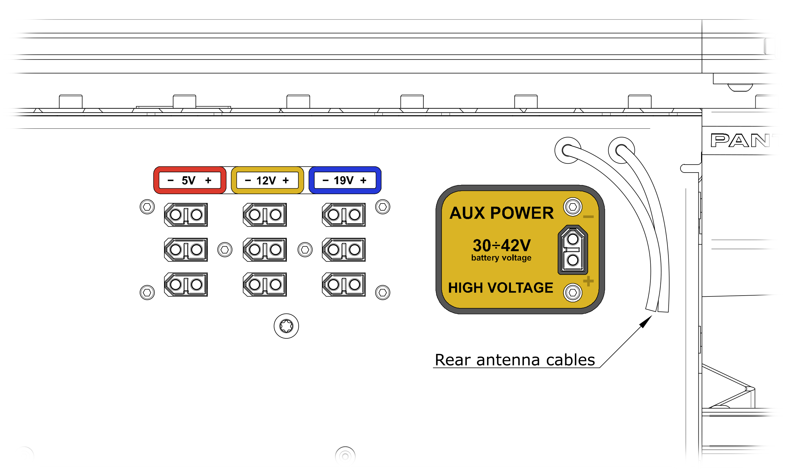
To meet the user's needs, the robot is equipped with 10 high-current electrical connectors that are able to provide up to 720 W of electrical power to the user's devices. The supply voltages available on the User Power Panel are:
- 5 V limited to 15 A, split into 3x female XT60 connectors,
- 12 V limited to 25 A, split into 3x female XT60 connectors,
- 19 V limited to 10 A, split into 3x female XT60 connectors.
- AUX Power which is the Battery voltage (32 - 42 V) rated at 10 A max. This output is disabled by default. AUX Power can be enabled and disabled separately from the Built-in Computer via a ROS service
/panther/hardware/aux_power_enable. See section Panther ROS 2 API for more details.
The total power from 5 V, 12 V, and 19 V outputs is limited to 360 W of power.
One 19 V output is used by an optional User Computer and one 12 V output is used by a Router.
These coaxial antenna cables are only present with the ANT01 option. In the ANT02 option, these wires are absent. Read more about in in the Panther Options section.
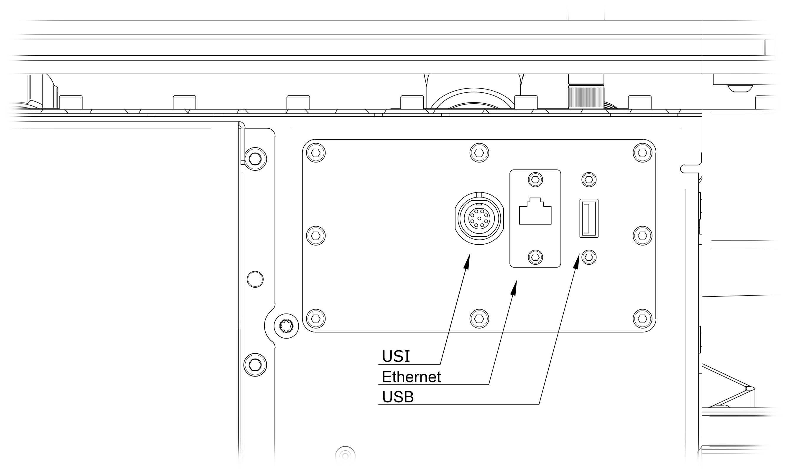
Communication Panel
On the Rear Panel, there are sockets for connecting the Battery and communication with the robot. By default, there are Ethernet and USB connectors for the Built-in Computer and the User Safety Interface (USI) connected to the Emergency Management:
Fuse Panel
Only Panthers with version 1.23 and newer are equipped with Fuse Panel. For older robots fuses are not user-replaceable.
For Panthers with BAT02 module panel can accessed only after removing battery module.
Fuse Panel is located on the rear, above battery module. It is equipped with two 5A fuses in MINI standard and socket for wireless charging module (WCH01). Each fuse is protecting a single charge line leading to battery module and can be replaced by user.
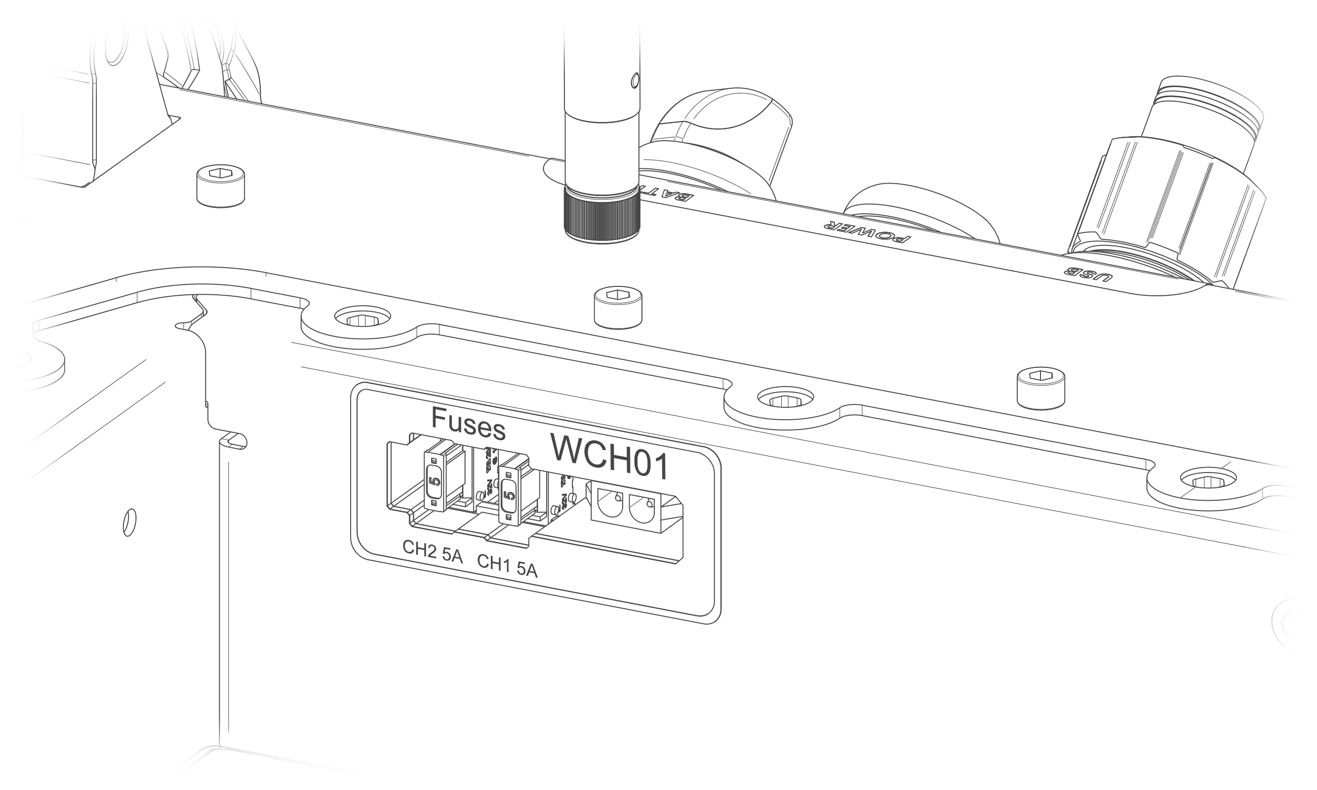

Connecting not approved devices or changing fuses to different values can damage the robot!
The robot's volume has been divided into three parts. The central space named the User Compartment, with a volume of approximately 14.5 liters (3.8 gallons) is dedicated for the user's components and electronics, as well as the robot's Battery. This part of the robot has the same water and dust tightness class as the robot. By default, there is the PC02 User Computer and the Router responsible for both the wireless communication of the robot and the wired connection of computers and sensors within the robot.
Above this shelf, two User Panels have been led into this space. A panel distributing electric power for the user:


The supply voltages available on the User Power Panel are:
- 5 V limited to 15 A (3x female XT60),
- 12 V limited to 25 A (3x female XT60),
- 19 V limited to 10 A (3x female XT60).
The Communication Panel with the rest of the robot (as standard, it is an Ethernet connector to the Built-in Computer):


The front and rear spaces are occupied by motors and built-in electronics. It is usually not necessary for these spaces to be accessed by the user. Opening them is mainly meant for service work.
Access to the User Compartment
To access the components inside the User Compartment, pivot the top rails by removing 2x shoulder screws and 2x nyloc nut. Then unscrew the Cover (18x DIN912 M5x12).
Running cables through Cover
Providing communication and power to devices mounted on Panther's railing is done by cable glands mounted through robot's Cover. In case of Panther ordered with sensors all customization is done by Husarion before shipping, however it can also be done by the user later on. Below is quick guide how to do it.
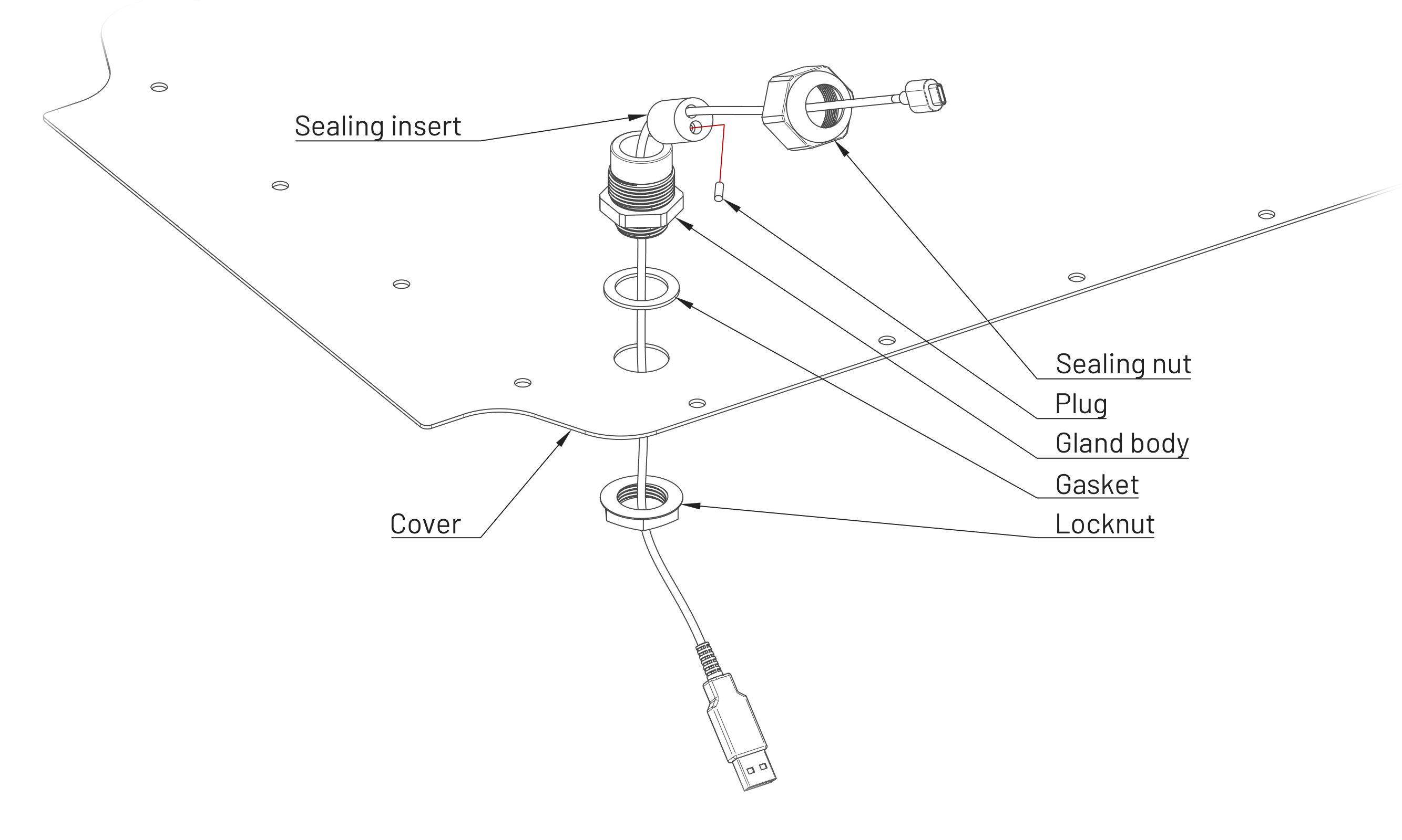
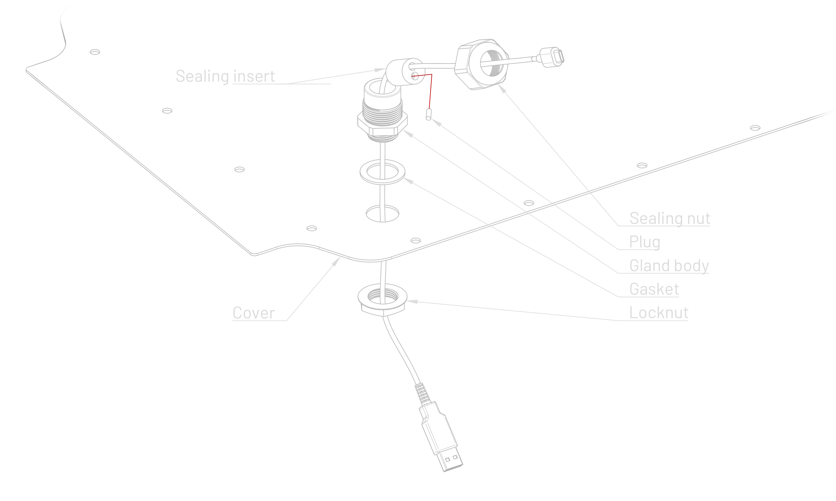
Cable gland
Cable glands are industrial standard for passing cables through enclosures and are used on Husarion UGVs. Using parts with IP rating as high as an UGV or higher allows to retain rated IP protection of an UGV. Typical application is shown below:
Common cable gland manufactures are: TE Connectivity, LAPP, Phoenix Contact.
Cable gland size
Husarion uses metric type for all customization work and, as such, only it will be described. However PG type can be used - consult cable gland manufacture's data sheet for more information.
Required size of cable gland is dictated by cable diameter and (if cable is assembled with connectors) it's connector dimensions. Multiple cables can be passed through single cable gland with proper insert. Smallest internal diameter of a cable gland (usually it is gland nut) has to be bigger then connector's diagonal. Table below shows minimum size of cable gland for a few common connectors.
Smaller cable gland size can be used if connector can be installed after passing cable through it.
Always consult data sheet or measure parts before installation! Your connector and cable gland might be different.
| Connector | Connector diagonal (typical) | Minimum cable gland size (typical) |
|---|---|---|
| USB type A | 17 mm | M25 |
| USB type B | 15 mm | M25 |
| USB mini-B | 15 mm | M25 |
| USB micro-B | 12 mm | M20 |
| USB type C | 12 mm | M20 |
| SMA / RP-SMA | 10 mm | M16 |
| Ethernet (RJ-45) | 17 mm | M25 |
| M8 | 13.5 mm | M25 |
| M12 | 20 mm | M32 |
For larger connectors split cable glands systems are recommended such as: Icotek KVT-ER or PFLITSCH UNI Split Gland. Split cable glands with rectangular cut-outs are also available.
Even when using split cable gland, connector has to go through hole in Cover!
Sealing inserts
Sealing inserts are used to achieve correct seal between cable and gland body. There are three parameters, which are used to choose one: cable gland size, cable diameter and number of passthrough. Sometimes only sealing insert with multiple holes is available for required cable diameter. In such case unused holes are sealed with a plug - which is available as cable gland accessory.
Some sealing inserts are pre-cut on long axis to allow insertion on a cable without passing through connectors. Such cut can also be done by a user. Ensure clean cut by using a sharp tool.
Mixing parts between series and manufactures can cause lower IP rating then in specification.
Cable gland installation instruction
If your robot already has a cable gland it might be possible to add a cable to it by only changing sealing insert.
- Select proper cable gland for your cable - see details above.
- Remove the Cover from UGV. Perform next steps away from robot, to avoid debris inside.
- Choose a spot on the Cover, where there will be no collisions with other elements inside User Space and on Rails.
- Use center punch to mark the spot.
- Drill and deburr the hole. For thin sheet metal, as used in a Cover step drill is recommended for drilling.
- Install cable gland with a cable. Apply enough torque as per gland manufacturers recommendations to locknut and sealing nut, to compress gasket and sealing insert.
Make sure, that cable is firmly held by cable gland - only then proper IP rating will be achieved.
Service Spaces
- Panther v1.2
- Panther v1.0 - v1.06
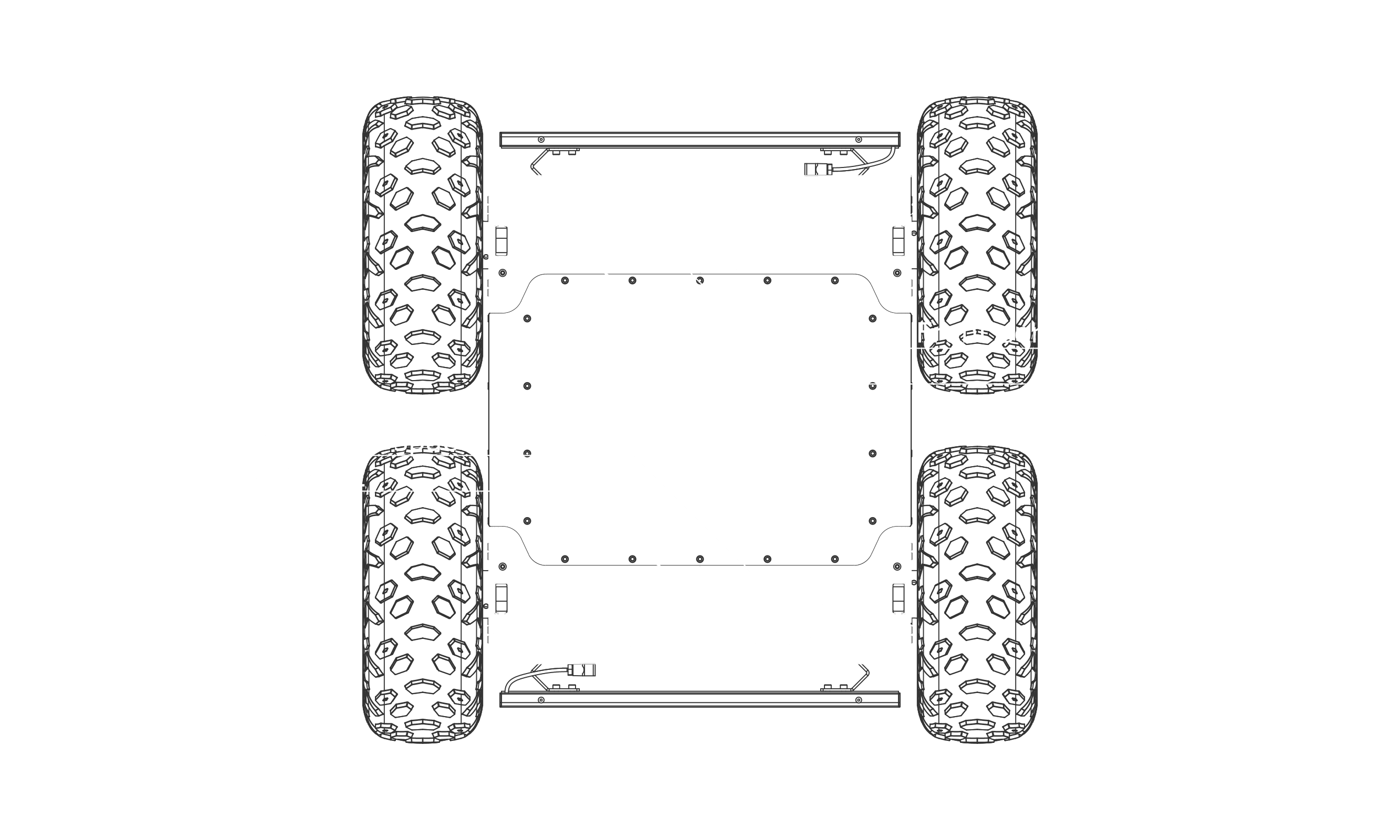
The four remaining spaces around the User Compartment are intended for the internal components of the robot and some elements of the additional option sets. In this case, the relevant information can be found in the description of the given option in Panther Options.
It is usually not necessary for the user to access those spaces. Opening them is mainly meant for service work.
It is advised to remove the battery before accessing service spaces to prevent electrical hazards and potential damage. Cutting off power by putting the Battery Switch in the OFF position is NOT the same as taking out the Battery. If power is required during maintenance (e.g. upgrading motor drivers), be extremely cautious. Ensure no metal objects, such as screws, fall into the service space as this can cause damage to the robot.
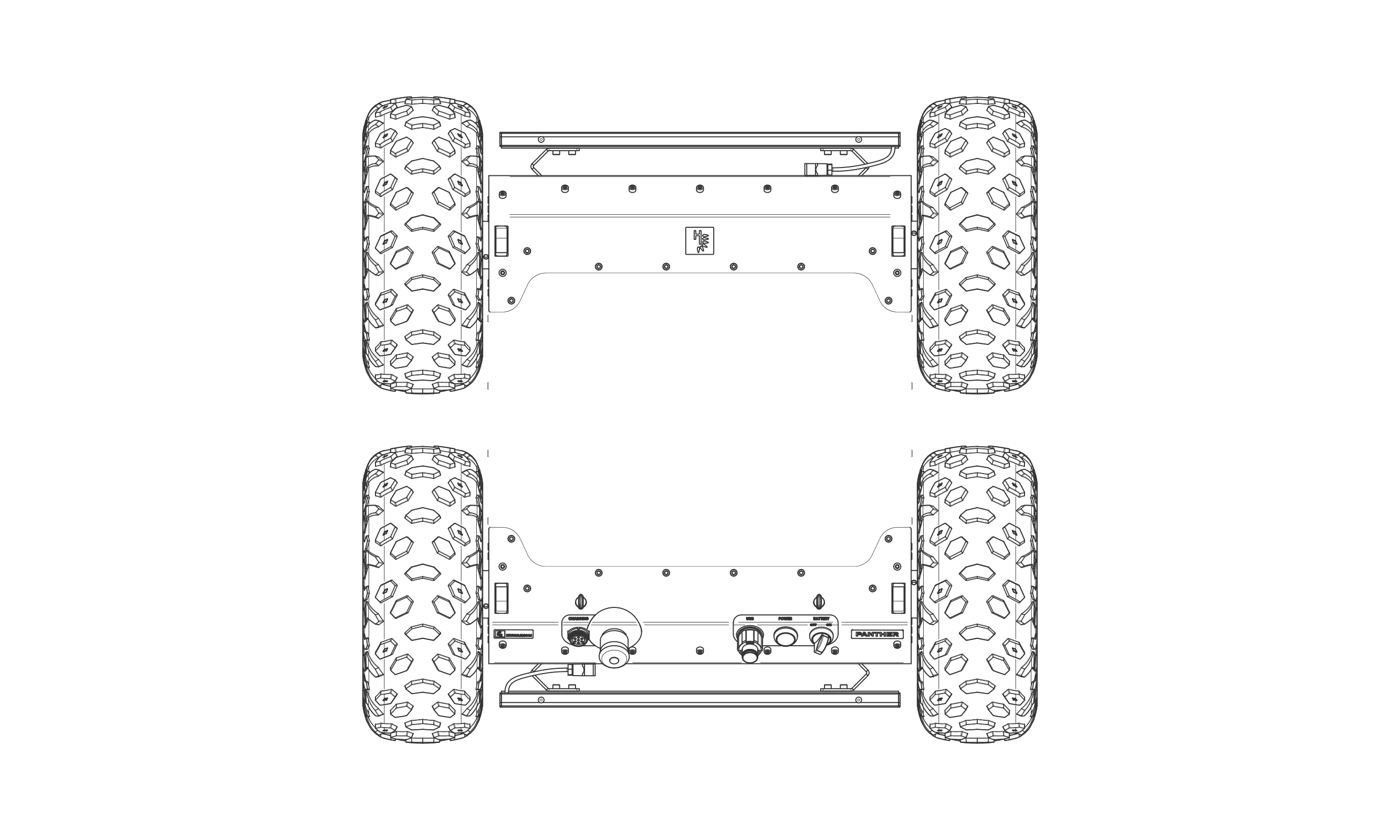
Access to the Front and Rear Service Spaces
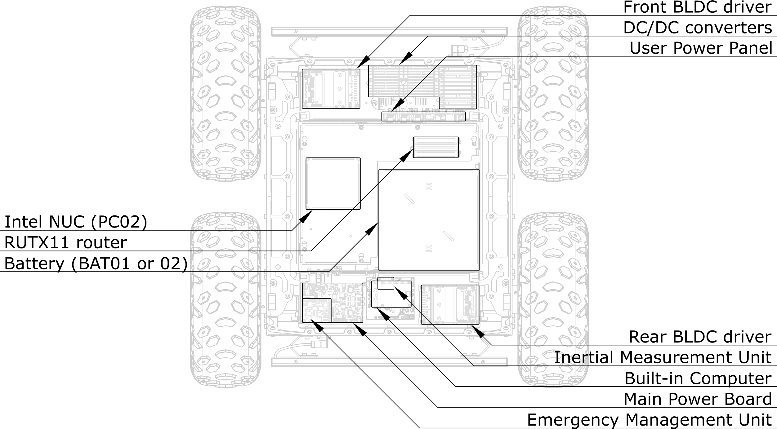
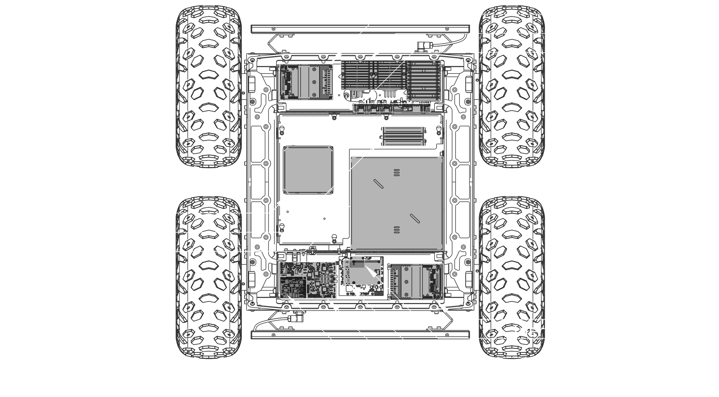
The Front and Rear Service Spaces are occupied by motors and built-in electronics.
To access the components in the Service Spaces, pivot the Mounting Rails by removing 2x ISO 7379 M6x30 shoulder screws with DIN 986 M6 nyloc nuts. Then unscrew the Front Deck (with the Husarion logo) or the Rear Deck (with the Emergency Button). Each is fastened with 15x DIN912 M5x12.
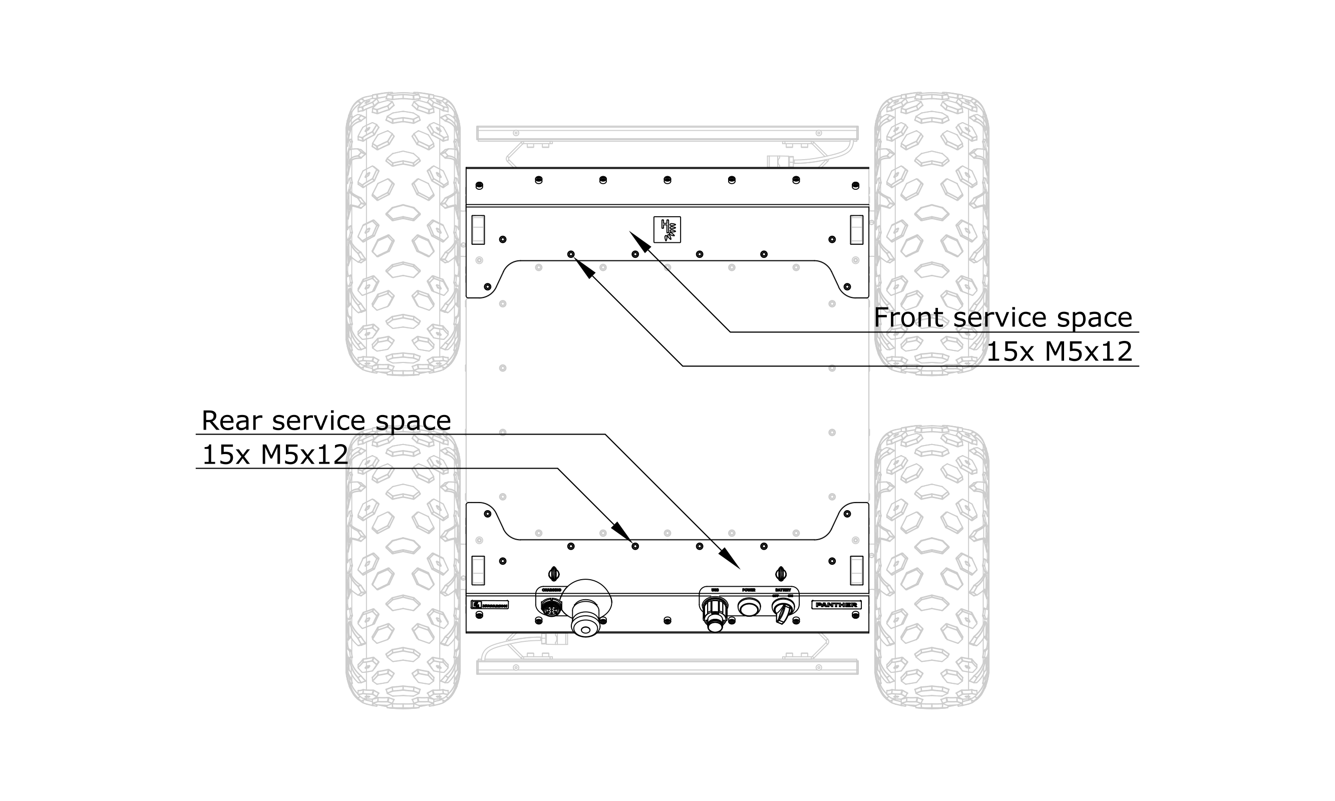
Under the Front Deck, you will find among others standard power converters (5 V, 12 V, 19 V), distribution of higher voltages for the user, high voltage converter (24 V / 48 V) connection, front motor controller, and the Fan connection. Under the Rear Deck, you will find among others a Battery connector, the Built-in Computer with its microSD card, the Bumper Lights driver, the Power Board, the Charging Socket line and Rear Panel buttons connections, the rear motor driver, and antenna connections.
Access to the Side Service Spaces
Stringers (the structural elements located on the sides of the robot) also contain subassemblies.
To access these spaces, it is necessary to remove the wheels on the relevant side. Read more about removing wheels in the article Panther WH03 - Wheel Swap. Then you need to remove the Side Cover which is fastened with 12x bolts DIN912 M5x16.
By default, the Right Stringer has the Fan used for forced air circulation inside the robot (the Fan can be controlled via ROS service /panther/hardware/fan_enable). There are also cable harnesses in both Stringers. For some of Panther's options, additional equipment may be installed in these spaces. In such cases, the necessary information can be found in the description of the option in the Panther Options section.
To ensure the tightness of the robot, make sure that there are no foreign objects on the seal when assembling the skin element and tighten the bolts with a torque of 4 - 5 Nm.
To access the components in the Service Space, pivot the Mounting Rails by removing 2x shoulder screws and 2x nyloc nut. Then unscrew the Front Deck (the one with the Husarion logo) fastened with 17x DIN912 M5x12 screws.
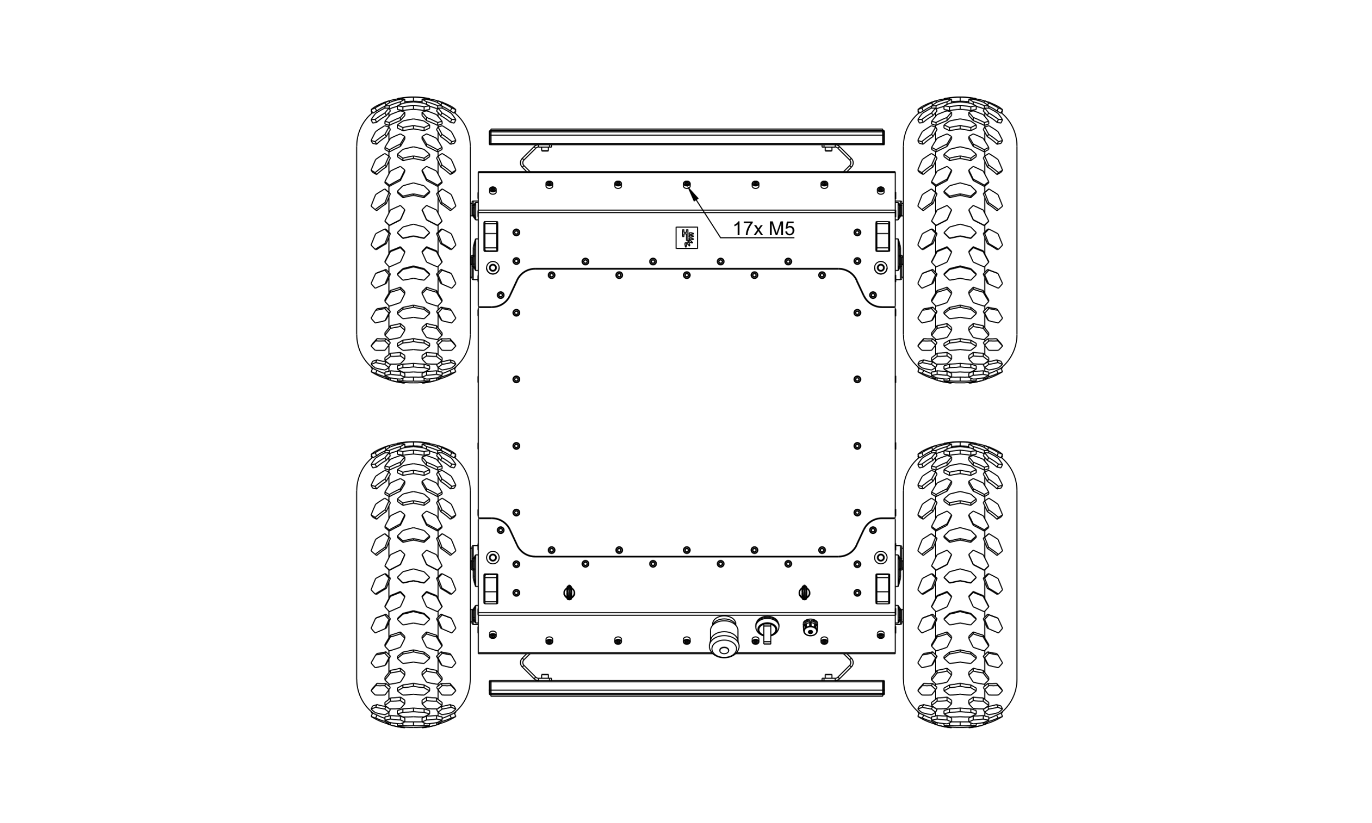
To ensure the tightness of the robot, make sure that there are no foreign objects on the seal when assembling the skin element and tighten the bolts with a torque of 4 - 5 Nm.
CAD Models
To facilitate the work with the project based on the Panther platform, we have prepared CAD models for download in three extension formats:
- Panther v1.2
- Panther v1.0 - v1.06
Software Guide
The Panther UGV’s ROS 2 driver runs on a Built-in Computer powered by a customized Ubuntu-based operating system with a real-time kernel.
Interaction with Panther's hardware is primarily facilitated through the Robot Operating System (ROS), with all drivers developed in ROS. The source code is available in the GitHub repository husarion/husarion_ugv_ros. The platform supports both ROS and ROS 2, offering consistent APIs and behavior across both versions.
User-level ROS 2 software is intended to run on a separate user computer.
ROS is a set of software libraries and tools for building robot applications, offering a common framework for development. It is open-source, making it free to use and modify.
Software Resources
- ROS
- ROS 2
- ROS API - Learn about the robot API.
- Robot Management and Configuration - Tools and information for robot configuration during development.
- ROS Packages Overview - Detailed information on individual packages.
- ROS 2 API - Learn about the robot API.
- Robot Management and Configuration - Tools and information for robot configuration during development.
- ROS 2 Packages Overview - Detailed information on individual packages.
By default, Panther ROS is deployed using Docker, which simplifies deployment, management, and updates of the ROS system. While the default setup is within a Docker container, you can run Panther ROS drivers natively. Instructions are available on the husarion_ugv_ros GitHub page.
Natively built ROS packages do not include autostart functionality. Users need to add it, for example, by creating a systemd service.
The provided Panther ROS system is designed to compose all the basic functionalities of the robot. It allows to control of the robot with velocity commands and provides the user with odometry information, which can be used for robot localization. The Panther ROS system is also designed to monitor the robot's state and perform safety features that will prevent any hazardous behavior. The basic states of the robot are represented by the Bumper LED Animations. This allows the user to recognize if the robot is ready to operate or in E-stop mode, informs about the Battery state, or displays an animation indicating the occurrence of an error in the system. More detailed information about the state of the robot can be acquired using ROS topics. Errors in the system are also logged into the system and can be easily accessed using the Docker interface. The Panther ROS system includes a robot description, which can be used to visualize the robot with all its components.
The Panther ROS system is designed to be easy to use and maintain. It is also designed to be extensible so that it can be easily customized for different applications.
Launch System Analysis
This section provides an overview of the system launch times for the Panther robot version 1.23, ROS driver version 2.3.0, and RUTX11 firmware version RUTX_R_00.07.13.3. The measurements were conducted multiple times to ensure accuracy, and the results presented are averaged values.
RUTX11
| Description | Time (mm:ss) |
|---|---|
| LAN network availability. | 1:15 |
| Wi-Fi network availability. | 1:20 |
Built-in Computer
| Description | Time (mm:ss) |
|---|---|
| Full boot time (from pressing the robot's power button to full system readiness). | 1:18 |
| Boot time for RPi | 0:28 |
| Time from RPi boot to full system readiness. | 0:50 |
| Driver docker container startup time (from RPi boot). | 0:34 |
| Driver initialization time inside Docker. | 0:16 |
Autonomy reference stack
The husarion-ugv-autonomy template repository provides a Docker-Compose workspace that bundles all navigation-related nodes (Nav2), SLAM and the docking server required by Panther / Lynx.
| Path | Purpose |
|---|---|
compose.hardware.yaml | Launches navigation and docking containers on the real robot. Environment variables such as OBSERVATION_TOPIC, OBSERVATION_TOPIC_TYPE, CAMERA_* and SLAM are forwarded so you can point the stack at any LIDAR/camera without editing the file. Networking is set to host for zero-conf DDS discovery. |
compose.simulation.yaml | Adds a Gazebo container plus a components.yaml model layout. use_sim_time is preset, so clocks are synchronised automatically. |
config/ | Holds runtime parameters: nav2_params.yaml, pc2ls_params.yaml (planner, controller & point-cloud-to-laser tuning), components.yaml (where each sensor is mounted in simulation), docking_server.yaml, apriltag.yaml (dock poses and tag size) cyclonedds.xml (DDS QoS / discovery options) |
sensors/ | Optional compose fragments for bespoke drivers; drop in another file when the default containers do not cover your sensor. |
Helper commands (Justfile)
just dock DOCK_NAME        # Dock Husarion UGV to the charging dock using navigation stack
just dock-direct DOCK_NAME # Dock Husarion UGV to the charging dock without using navigation stack
just start-hardware        # Start navigation on User Computer inside Husarion UGV
just start-simulation      # Start Gazebo simulator with navigation stack
just start-visualization   # Configure and run Husarion WebUI
just stop-visualization    # Stop Husarion WebUI
just undock                # Undock Husarion UGV from the charging dock
Upstream ROS 2 code
Both navigation and docking containers are built from the husarion/husarion-ugv-autonomy:<distro>-<tag> image, which in turn packages the sources in husarion_ugv_autonomy_ros (SLAM, Nav2 bring-up, docking state-machine). Fork that repository if you need to change node logic and rebuild the image locally.
Sensor interface
The stack is sensor-agnostic: any device that publishes LaserScan or PointCloud2 (plus a TF to base_link) and any RGB-D/mono camera that publishes Image + CameraInfo can be used. Simply export the five environment variables listed in the README, or add a new service under sensors/ that runs your proprietary driver.
Extended notes
A detailed explanation of the architecture and customisation workflow is available in the blog post: https://husarion.com/blog/husarion-ugv-autonomy/
Network
Overview
Panther is equipped with a Teltonika RUTX11 router running open-source firmware OpenWRT, which provide the following interfaces:
Ethernet
- 1x WAN 10/100/1000 Mbps (by default configured as a LAN port)
- 3x LAN 10/100/1000 Mbps
- 3 ports are available for user equipment
Wireless
- Two radios (2.4GHz and 5GHz)
- Support for 802.11ac (Wi-Fi 5) with link rate up to 867 Mbps, fast roaming with 802.11r
- Works as access point (AP) and/or as a client/station (STA)
- External antennas with 2 dBi gain
Cellular
- Dual-Sim with fail-over
- LTE (4G) Cat 6
- External antennas with 3dBi gain (Panther Options - ANT02)
- Support for exact frequency bands depends on your locale. By default we equip Panther with version suitable for shipping address. For more details go here.
GNSS
- Support for GPS, GLONASS, Galileo and BeiDou
- Integrated into ROS GNSS API
- 1Hz refresh rate
- CEP-50 of 2.5m
- External antenna (Panther Options - ANT02)
Each form of connectivity can be part of an automatic WAN fail-over in order to provide a continuous connection to external services. More information is available on the manufacturer site. Some RUTX11 configuration scripts are available on our GitHub repository.
Safety
The robot has been equipped with solutions for the safe use of the equipment, both in the software and hardware layer.
Please take this chapter seriously. Inadequate and irresponsible using of the robot may cause damage to the device, the workplace, and people in the vicinity.
- Panther v1.2
- Panther v1.0 - v1.06
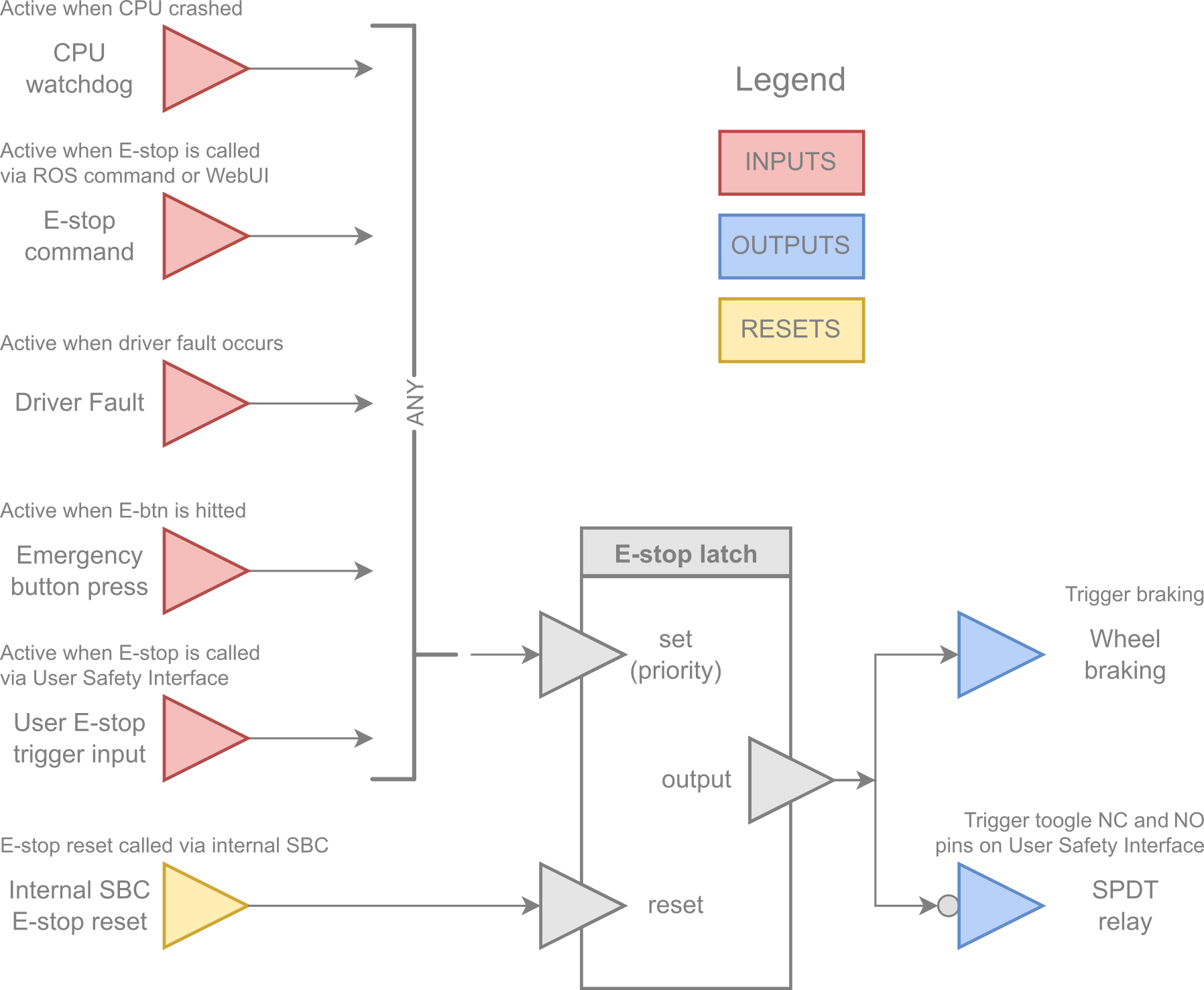
The robot is equipped with an Emergency Management (EMU). It is a system that takes control of the robot's components as well as its power in crisis situations. The EMU can stop the robot's movement, turn off the power of the user's device, or even turn off the entire robot if so configured. It also provides a dedicated electrical User Safety Interface (USI) led out to the User Space.
Due to the appearance of any trigger, such as a Built-in Computer's CPU crash or Emergency Button press, the EMU will call and latch the E-stop signal. This means that in such situations, for the further work of the robot, the problem should be resolved, and then the E-stop latch should be reset.
This chapter describes only the basic default EMU configuration, however, the system is configurable. To learn more about the possibilities and how to configure them, visit a separate article: Emergency Management Unit.
Hardware
- Panther v1.2
- Panther v1.0 - v1.06
Emergency Button
On the rear side of the robot, there is a red push button. Pushing the Emergency Button causes:
- activate the E-stop signal and latch it,
- actively brake the robot using motors,
- toggle a SPDT relay (external E-stop output).
These actions are the default EMU configuration. To learn more about the possibilities and how to configure it, visit a separate article: Emergency Management Unit
User Safety Interface (USI)
USI is an electrical hardware interface for EMU designed to integrate Panther with the user's equipment. This thread is covered in detail in the Emergency Management article in the chapter User Safety Interface.
Emergency Button
On the rear side of the robot, there is a red push button. Pushing the Emergency Button completely cuts off the power to the device.
Cutting off power may cause data loss on the Built-in Computer as well as on User Computer!
Transporting Panther
Panther is shipped in a wooden box for two reasons: to protect the robot itself, and to comply with transportation safety regulations for batteries. Li-Ion batteries with a capacity of over 100 Wh are considered dangerous goods. As long as the product with such a battery is properly packaged and marked, it can be transported by various means, including air transport.
If you consider transporting Panther to a remote location, we recommend that you keep the wooden box with the UN3481 marking and Class 9 (batteries) symbol. You will also need to confirm with your carrier that you are working with dangerous goods. For more details, please contact us at support@husarion.com
Before shipping, disarm Panther by setting all switches to the OFF position and pressing the Emergency Button. Also, the Battery charge level should be below 30% (35V). The tires pressure shall be about 1.5 bar for air transportation and 1 bar for ground/sea transport.
Docs and links
All helpful documents and links in one place:
- Panther v1.2
- Panther v1.0 - v1.06
- Safety Instructions - to avoid malfunctioning or damaging your Panther, please read this safety manual before use
- Husarion limited warranty terms and conditions
- Panther Schematic Block Diagram - basic robot components and connections between them
- Panther Overall Dimensions - three basic projections of the platform in all wheel options
- Panther Power Consumption and Run Time - description of Panther power consumption and run time in different working conditions
- Panther WH03 - wheel swap manual - instructions for the WH03 package option, to swap between off-road and mecanum wheels
- Panther PC02 - installation manual - instructions for PC02 package option, to install User Computer
- Github Repository husarion_ugv_ros - Packages with ROS hardware drivers of the Husarion Panther robot
- Github Repository panther_msgs - Custom ROS messages and services for Panther
- Docker Image panther-docker - Docker image with a Panther ROS package
- Docker Image panther-gazebo - Docker image with Panther simulation in Gazebo-classic
- Github Repository husarion_components_description - URDF models of sensors and other components offered alongside Husarion robots
- Panther Troubleshooting - instructions for common issues
- Teltonika RUTX11 Manual
- Teltonika RUTX11 Datasheet
- Panther Options
- Safety Instructions - to avoid malfunctioning or damaging your Panther, please read this safety manual before use
- Panther Schematic Block Diagram - basic robot components and connections between them
- Panther Overall Dimensions - three basic projections of the platform in all wheel options
- Panther Origin Point and Center of Mass - robot projections with marked mass center
- Panther Power Consumption and Run Time - description of Panther power consumption and run time in different working conditions
- Panther WH03 - wheel swap manual - instructions for the WH03 package option, to swap between off-road and mecanum wheels
- Panther PC02 - installation manual - instructions for the PC02 package option to install User Computer
- Github Repository husarion_ugv_ros - Packages with ROS hardware drivers for the Husarion Panther robot
- Github Repository panther_msgs - Custom ROS messages and services for Panther
- Docker Image panther-docker - Docker image with a Panther ROS package
- Docker Image panther-gazebo - Docker image with Panther simulation in Gazebo-classic
- Github Repository husarion_components_description - URDF models of sensors and other components offered alongside Husarion robots
- Panther Troubleshooting - instructions for common issues.
- Teltonika RUTX11 Manual
- Teltonika RUTX11 Datasheet
- Panther Options