ROSbot XL Assembly
The Basic and Telepresence packages ship ready to use, no assembly required. The Autonomy, Manipulation, and Manipulation PRO packages are delivered unassembled — pick your package below.
- Autonomy
- Manipulation
- Manipulation PRO
Autonomy Package Assembly
These are the assembly instructions for the Husarion ROSbot XL Autonomy Package.
Follow the instructions below and perform the steps in the order given.
A ROSbot XL purchased with the Autonomy Package is delivered unassembled. The plastic case contains the ROSbot XL and its standard equipment; the cardboard boxes contain the lidar, the camera and all the components required to mount them on the robot.
To perform the steps described below, you will need basic tools such as Allen keys and/or a PH1 screwdriver. The Allen keys are supplied with the platform.
Assembling the camera
-
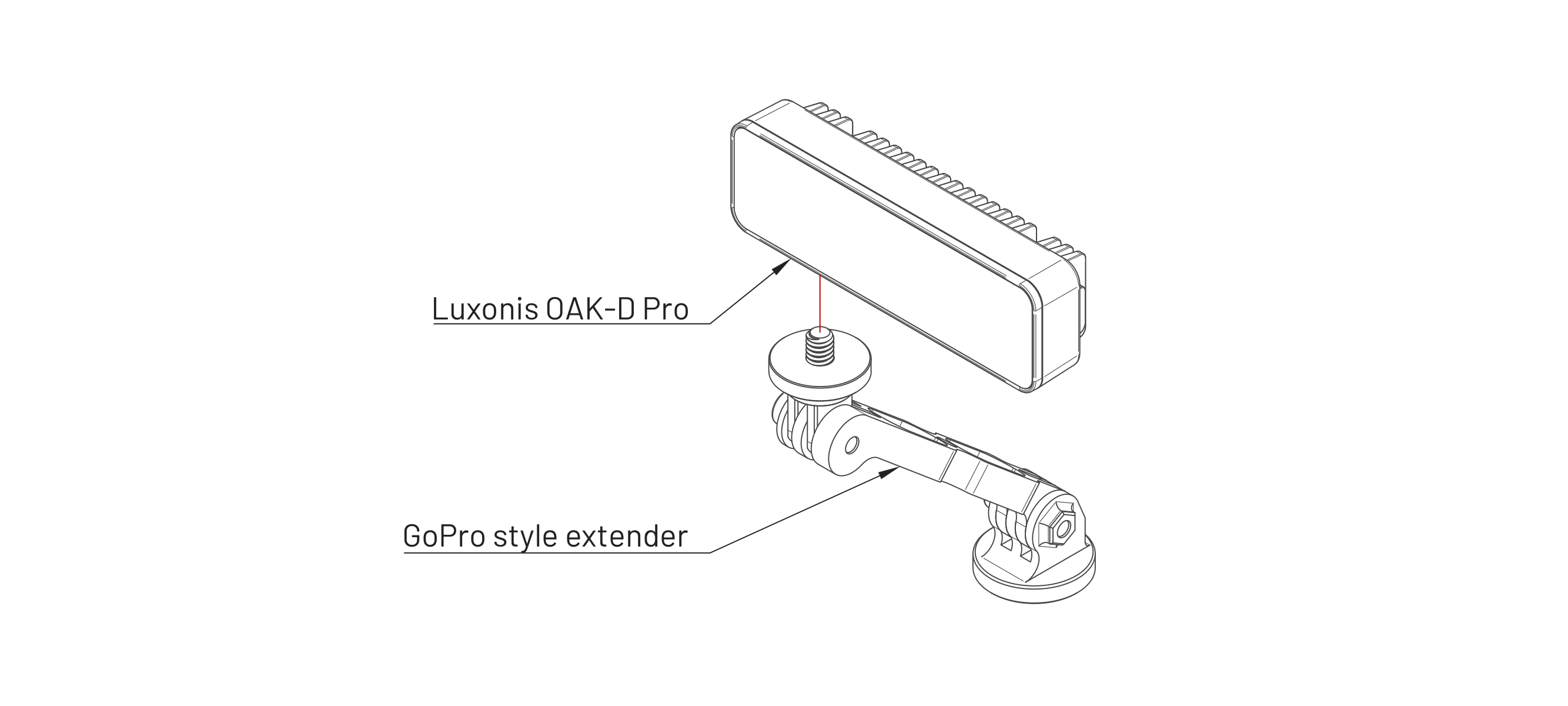
Screw the Luxonis OAK-D Pro camera to the GoPro-style mount.
Mounting on the ROSbot XL
-
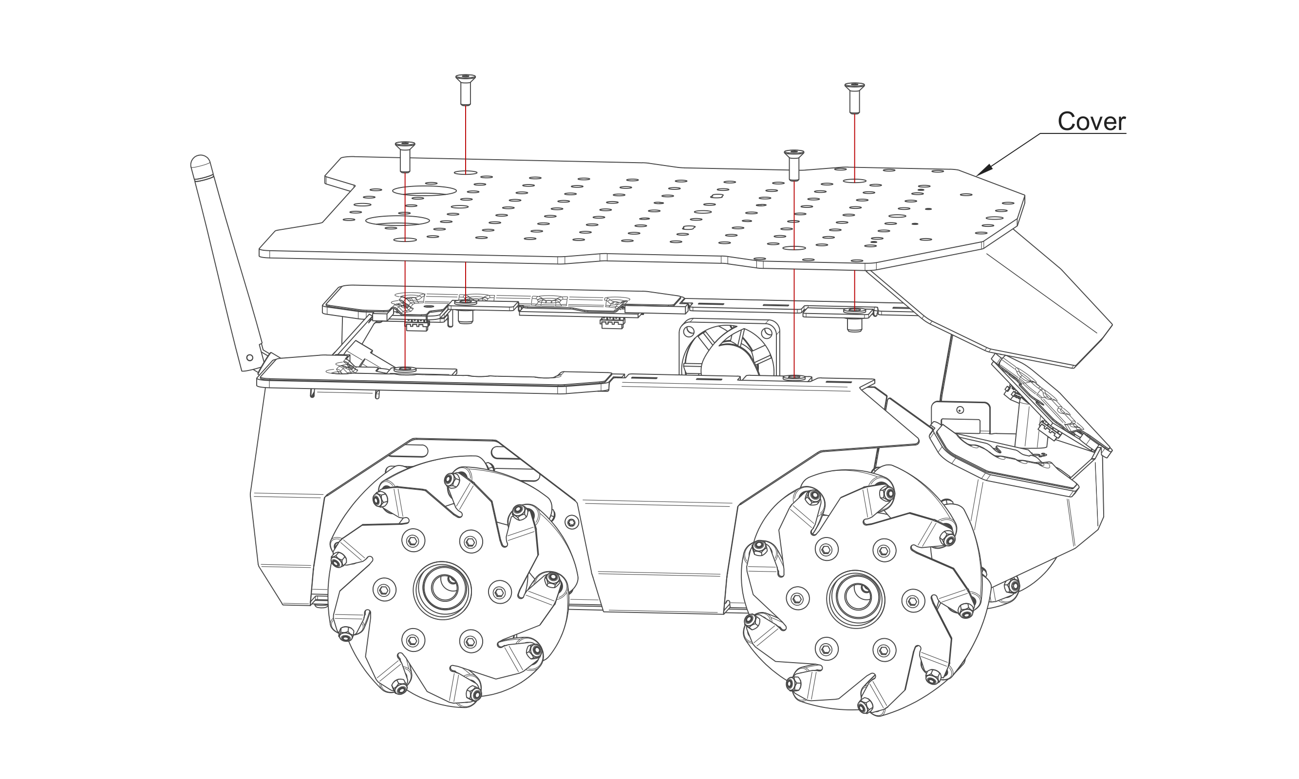
Unscrew and remove the Cover.
-
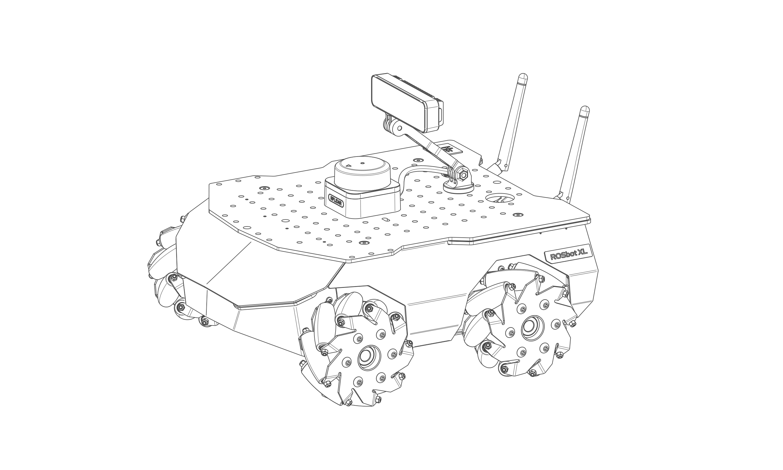
Mount the Luxonis OAK-D Pro camera and the Slamtec RPLIDAR S3 on the Cover.
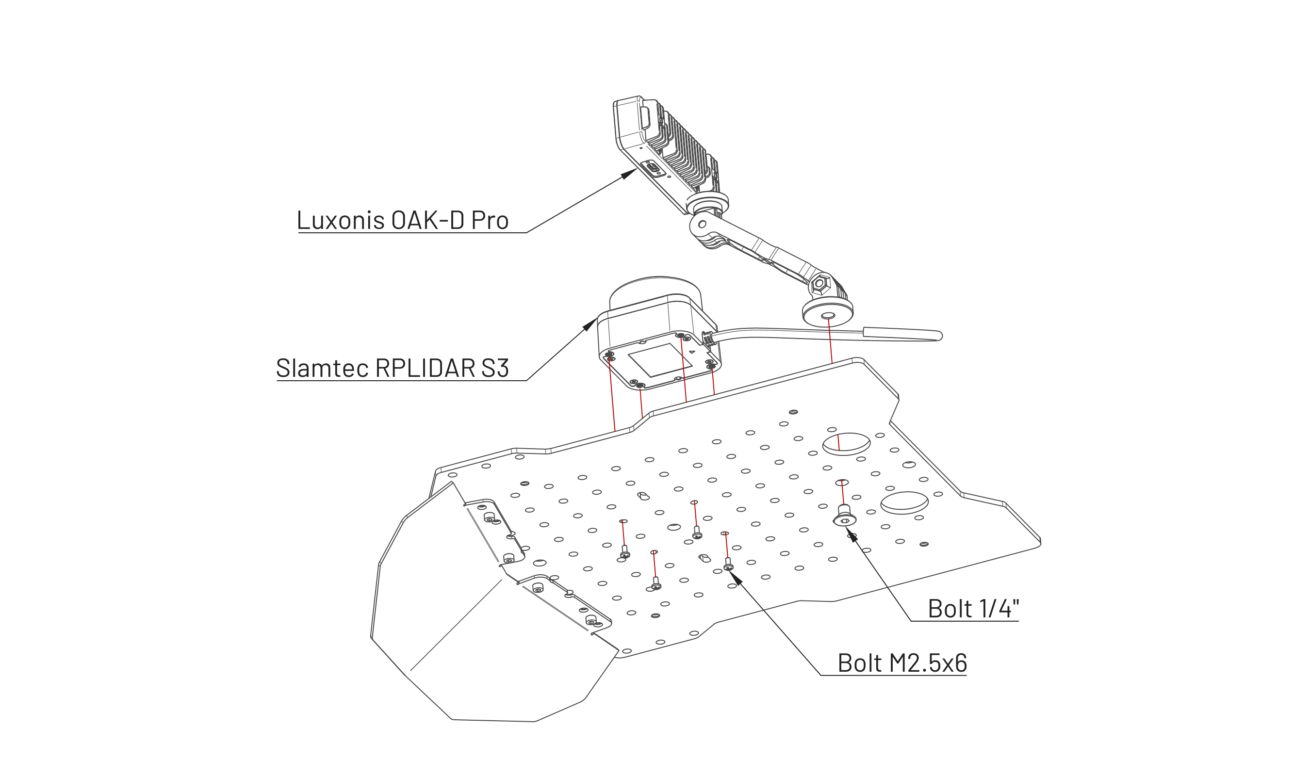
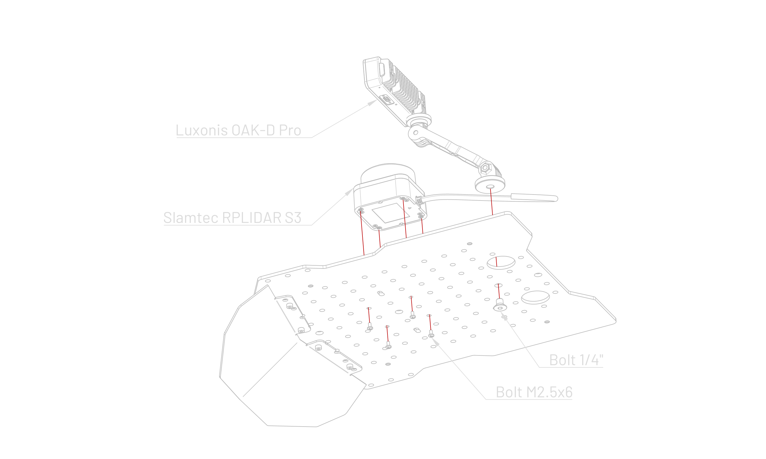
-
Connect the USB-A to USB-C cable to the Luxonis OAK-D Pro camera.
-
Insert the RPLIDAR USB adapter and the audio card with the adapter bracket into the User Shelf.
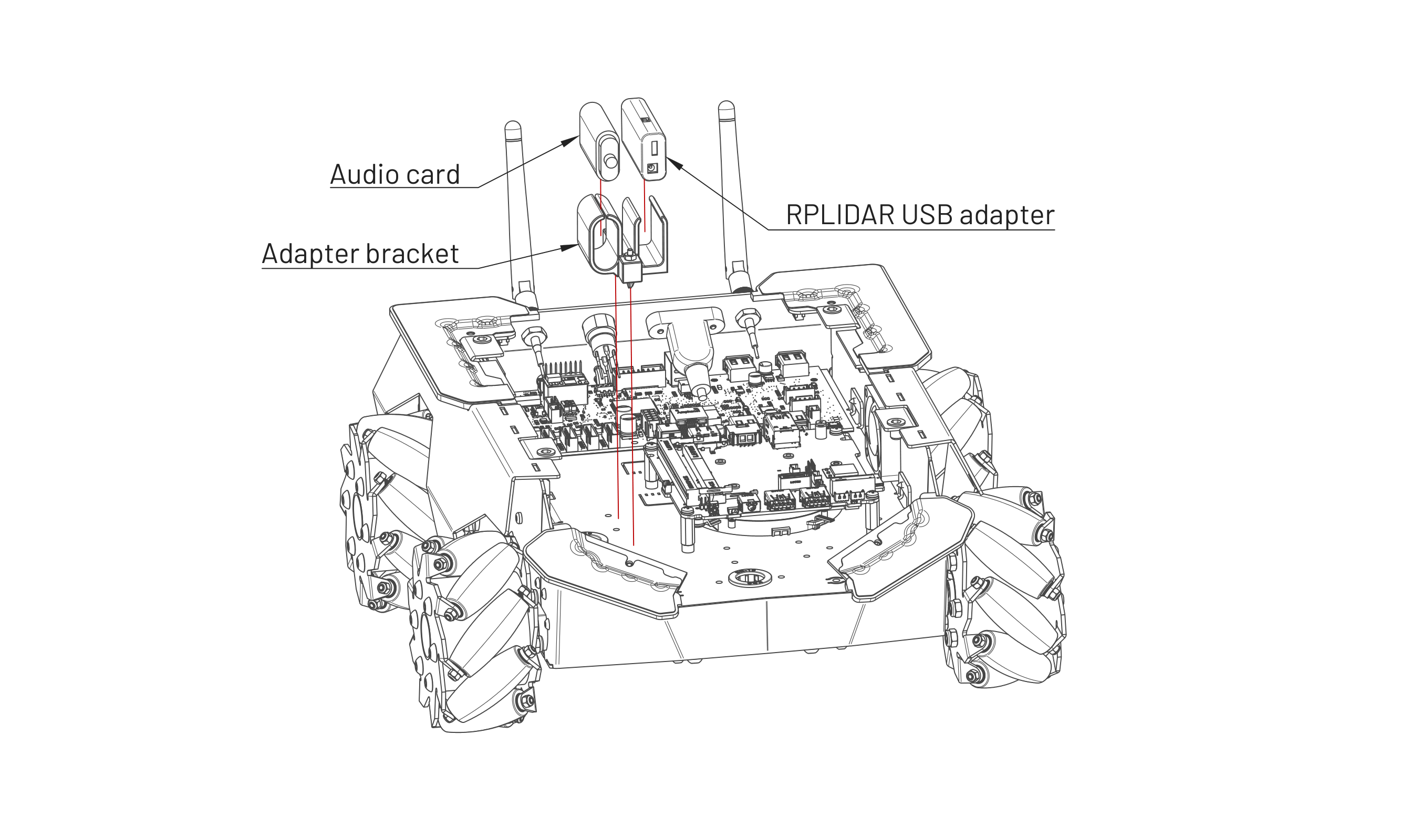
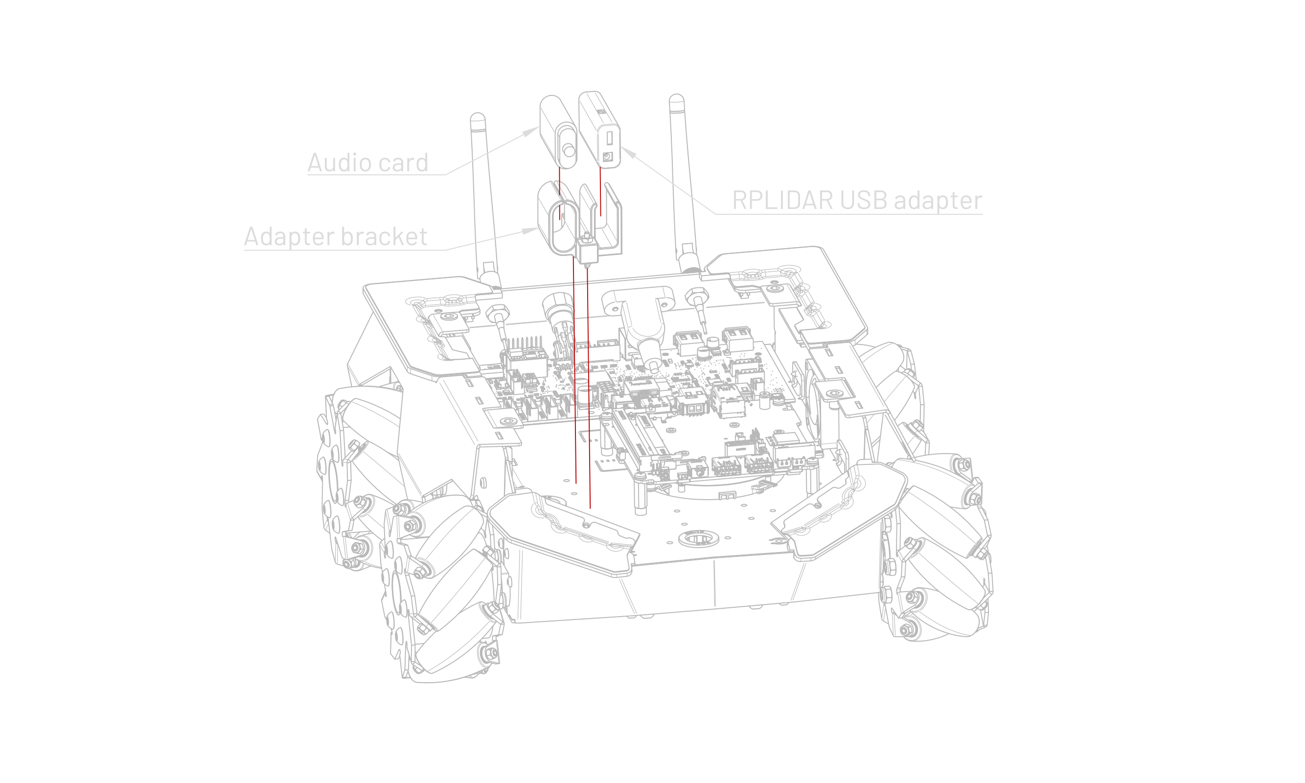
-
Connect the micro-USB to USB-A cable between the NUC computer and the RPLIDAR USB adapter.
-
Connect the RPLIDAR S3 to the RPLIDAR USB adapter.
-
Connect the USB-A plug of the camera cable to the NUC computer.
-
Mount the Cover on the ROSbot XL.
Software check
If the Luxonis OAK-D Pro camera has been installed correctly, the lsusb command run on the User Computer will show the following or similar output:
Bus 00x Device xxx: ID 03e7:2485 Intel Movidius MyriadX
or
Bus 00x Device 00x: ID 03e7:f63b Intel Myriad VPU [Movidius Neural Compute Stick]
For the lidar, the output should be:
Bus 00x Device 00x: ID 10c4:ea60 Silicon Labs CP210x UART Bridge
Manipulation Package Assembly
This is an assembly instruction for the Husarion ROSbot XL Manipulation Package.
Follow the instructions below and perform the steps in the order given.
A ROSbot XL purchased with the Manipulation Package is delivered unassembled. One cardboard box contains the ROSbot XL and its standard equipment; the other contains the arm and all the components required to mount it on the robot.
To perform the steps described below, you will need basic tools such as Allen keys. These keys are supplied with the manipulator and the platform.
Assembling the arm
-
Follow the instructions provided by the arm manufacturer. Stop before step 9.
-
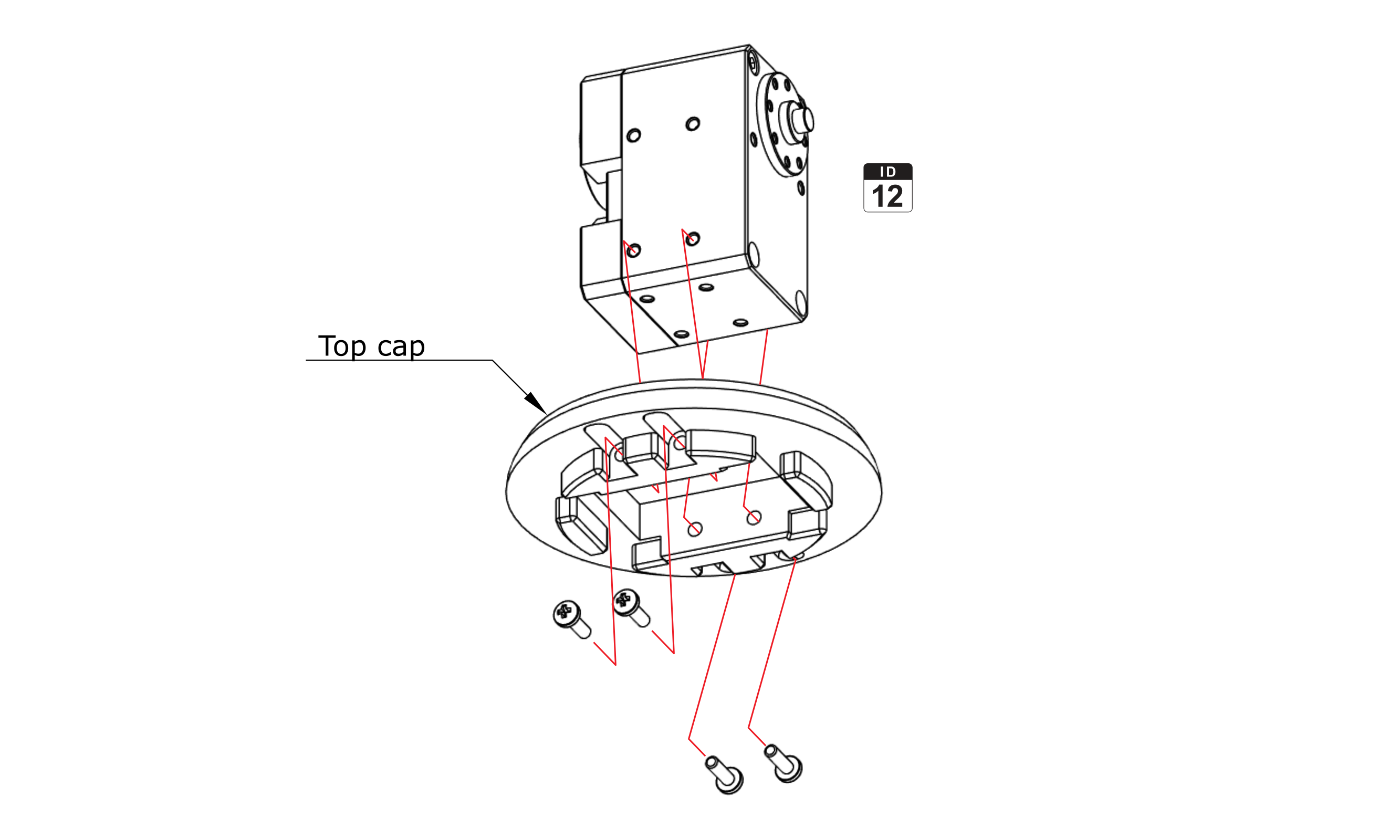
Slide the Top cap onto the DYNAMIXEL (ID 12) and fix it with four M2.5x8 panhead bolts.
-
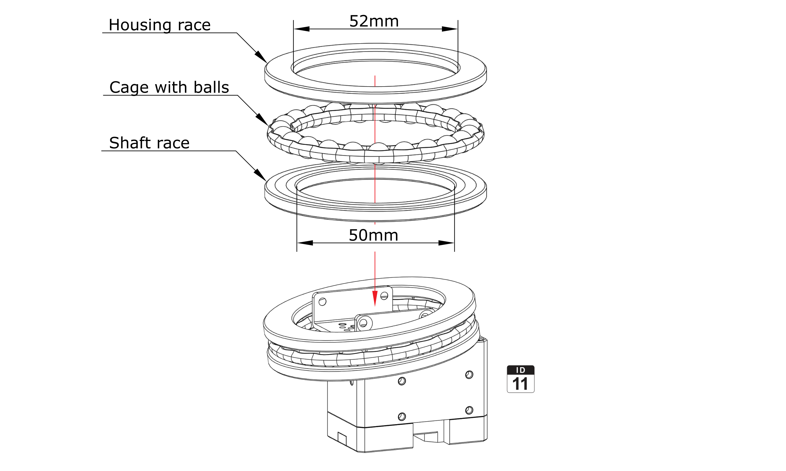
Place the Thrust bearing on the DYNAMIXEL (ID 11).
-
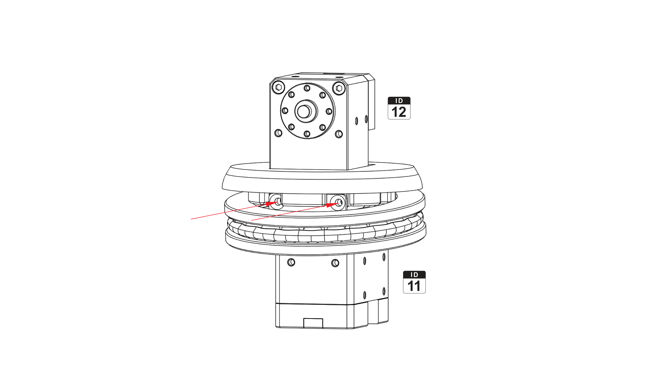
Insert the X-SP into the bolt holes of the DYNAMIXEL (ID 12) and attach it to the FR12-S102K using FHS-M2.5x14 screws. Pay attention to the horn align marking. As shown in the image below, rotate the FR12-S102K yoke into the position given so that you can reach the bolts with a key. Then rotate it by 180° to fix the other side.
-
Connect the DYNAMIXEL (ID 12) and the DYNAMIXEL (ID 11) using the CABLE-X3P-240.
-
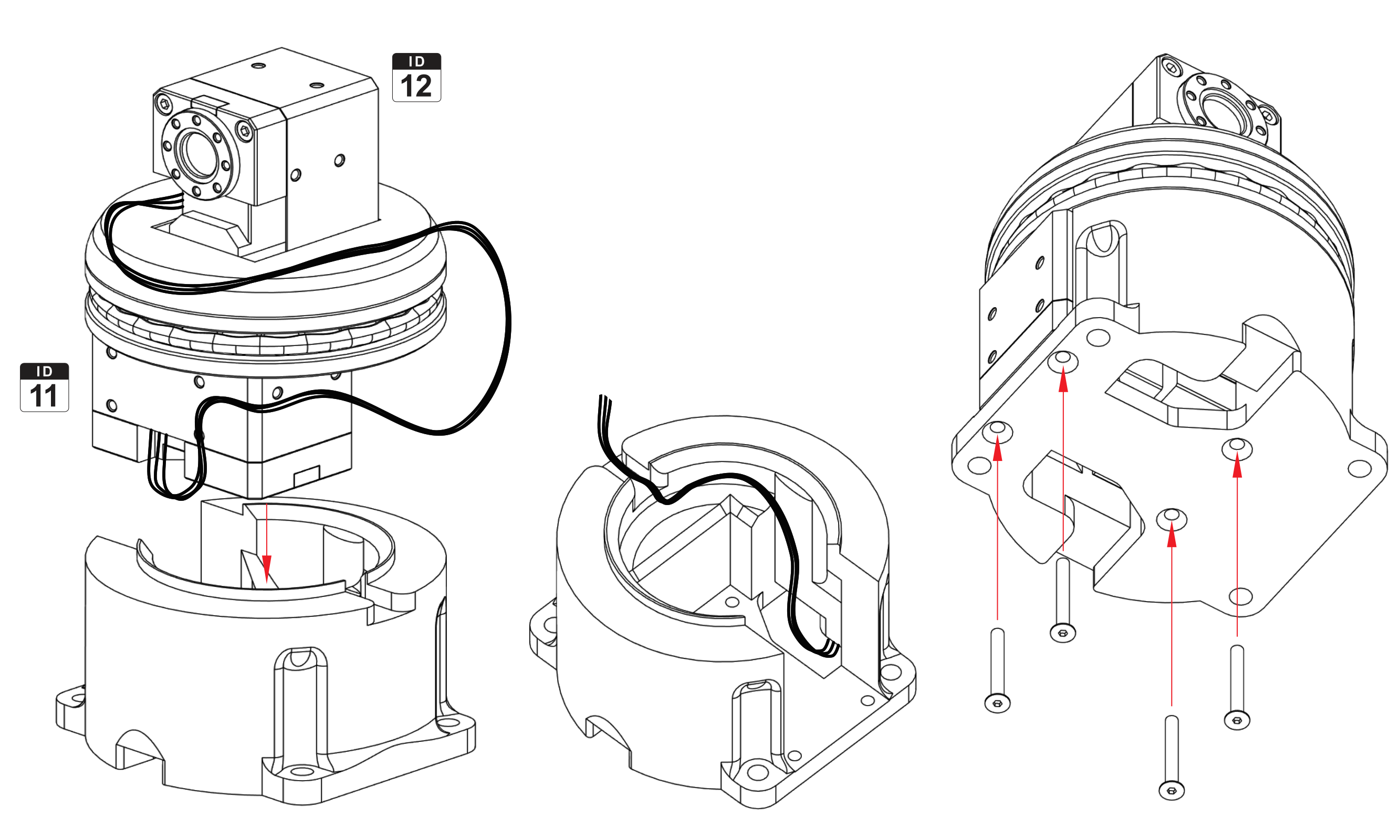
Slide the DYNAMIXEL (ID 11) into the Arm base. Pay attention to the cable routing inside the part and to the point where the cable leaves the housing through the notch under the bearing. Route the wires so that none of them is pinched. Fix the two parts together with four M2.5x21 countersunk bolts.
-
Continue with the manufacturer's instructions from step 10.
Mounting on the ROSbot XL
- Unscrew and remove the Cover.
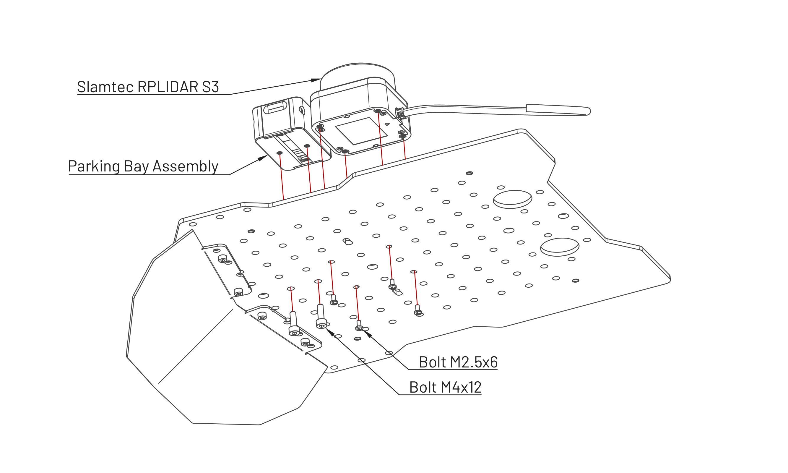
- Mount the Parking Bay Assembly and the Slamtec RPLIDAR S3 on the Cover.
- Connect the CABLE-X3P-380 to the DYNAMIXEL (ID 11).
- Install the Arm base on the Cover.
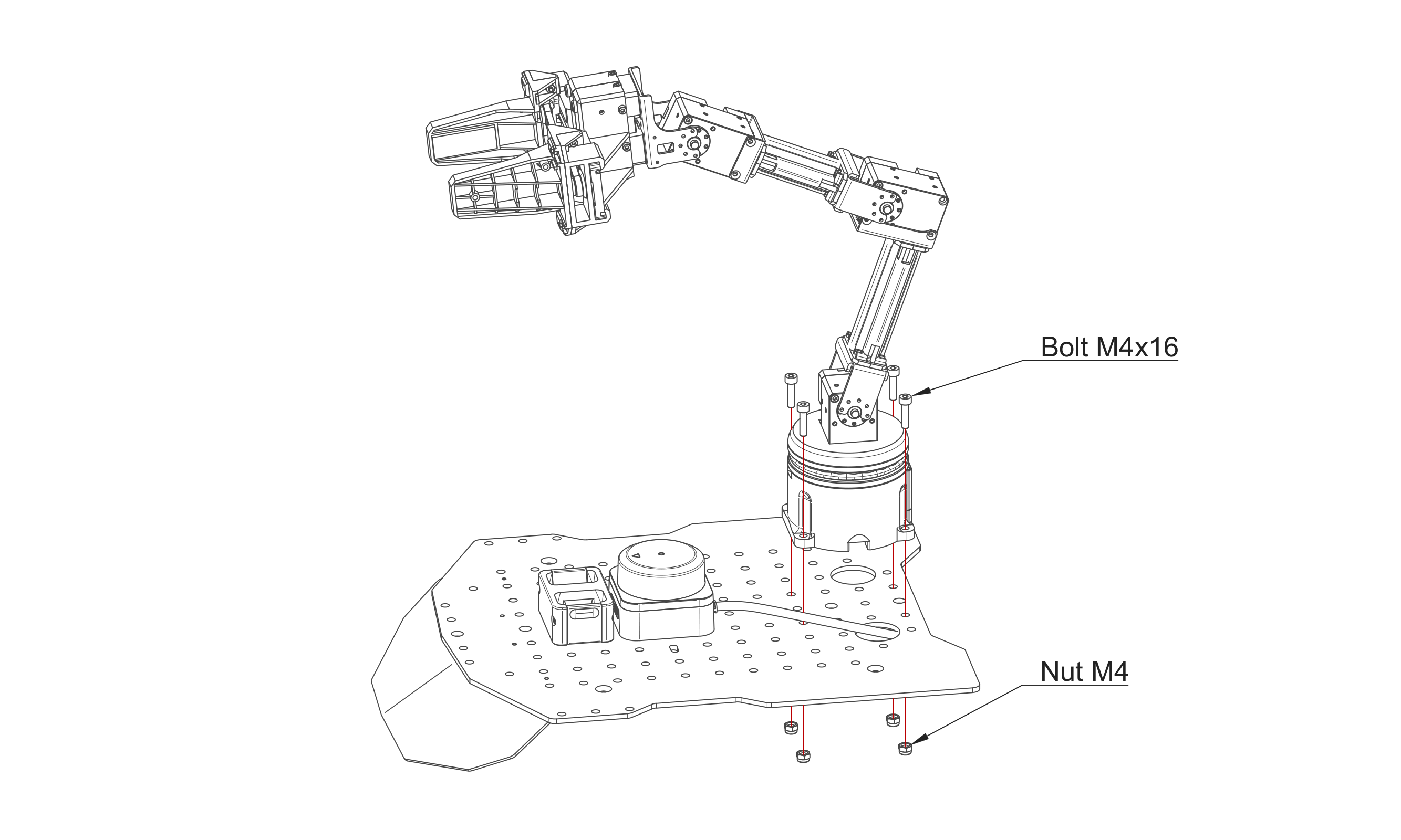
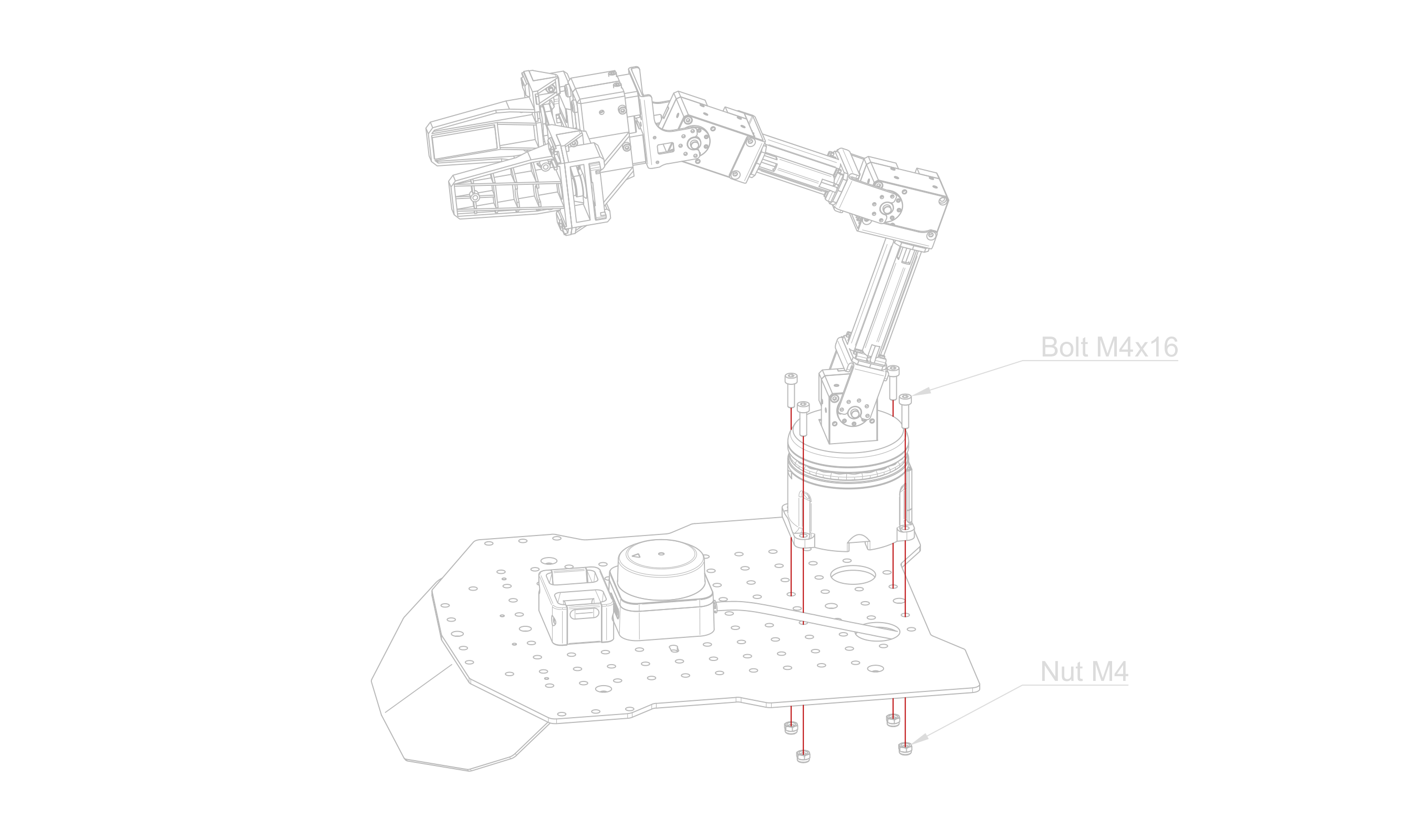
Depending on the production batch, some of the following steps (5 to 8) may already have been completed.
-
Connect the ROSbot XL Arm Board to the ROSbot XL Power Board and secure it with one M3x4 panhead bolt.
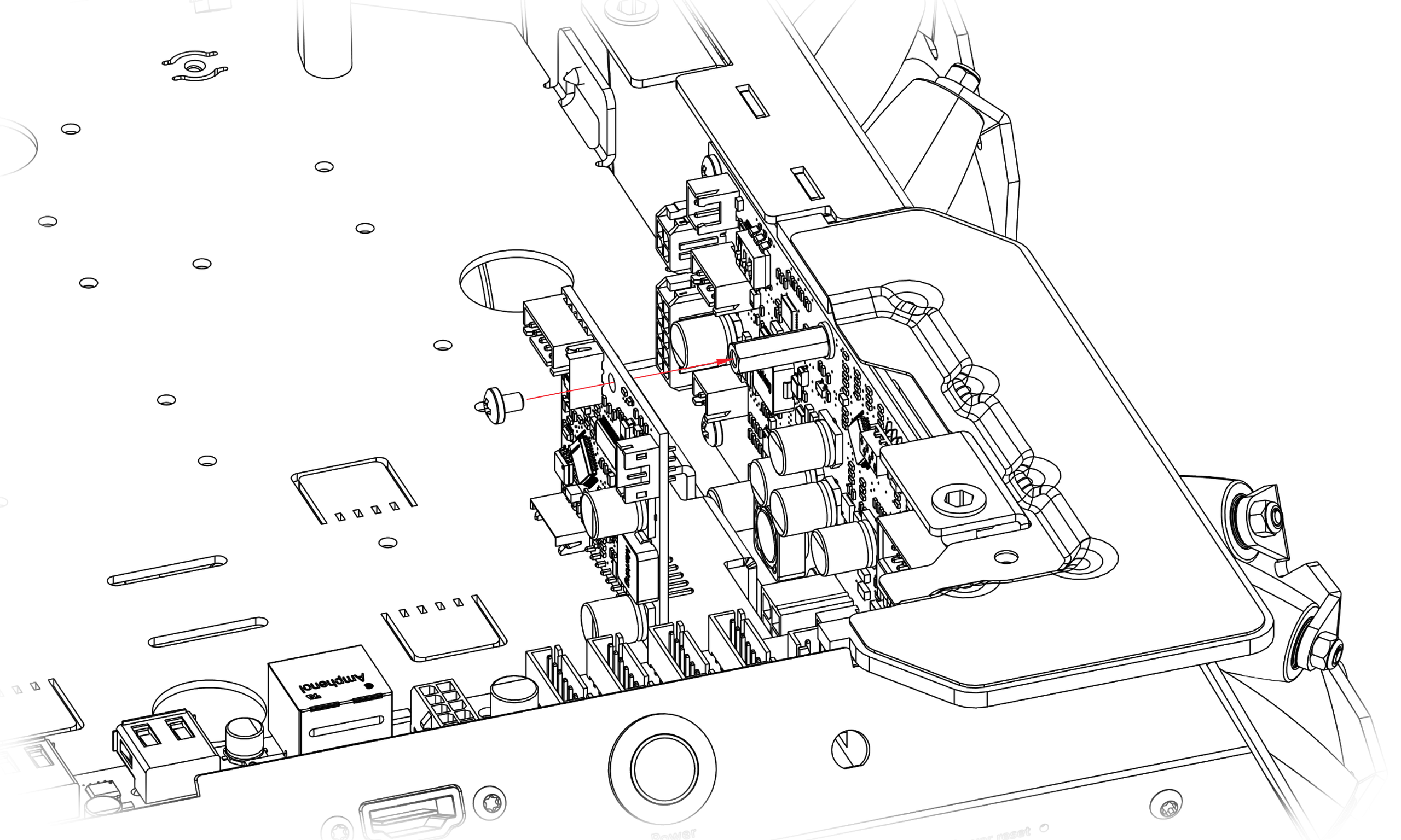
-
Connect the ROSbot XL Arm Board (CON1) to the ROSbot XL Digital Board (CON15) using the CABLE-JST-5-240.

-
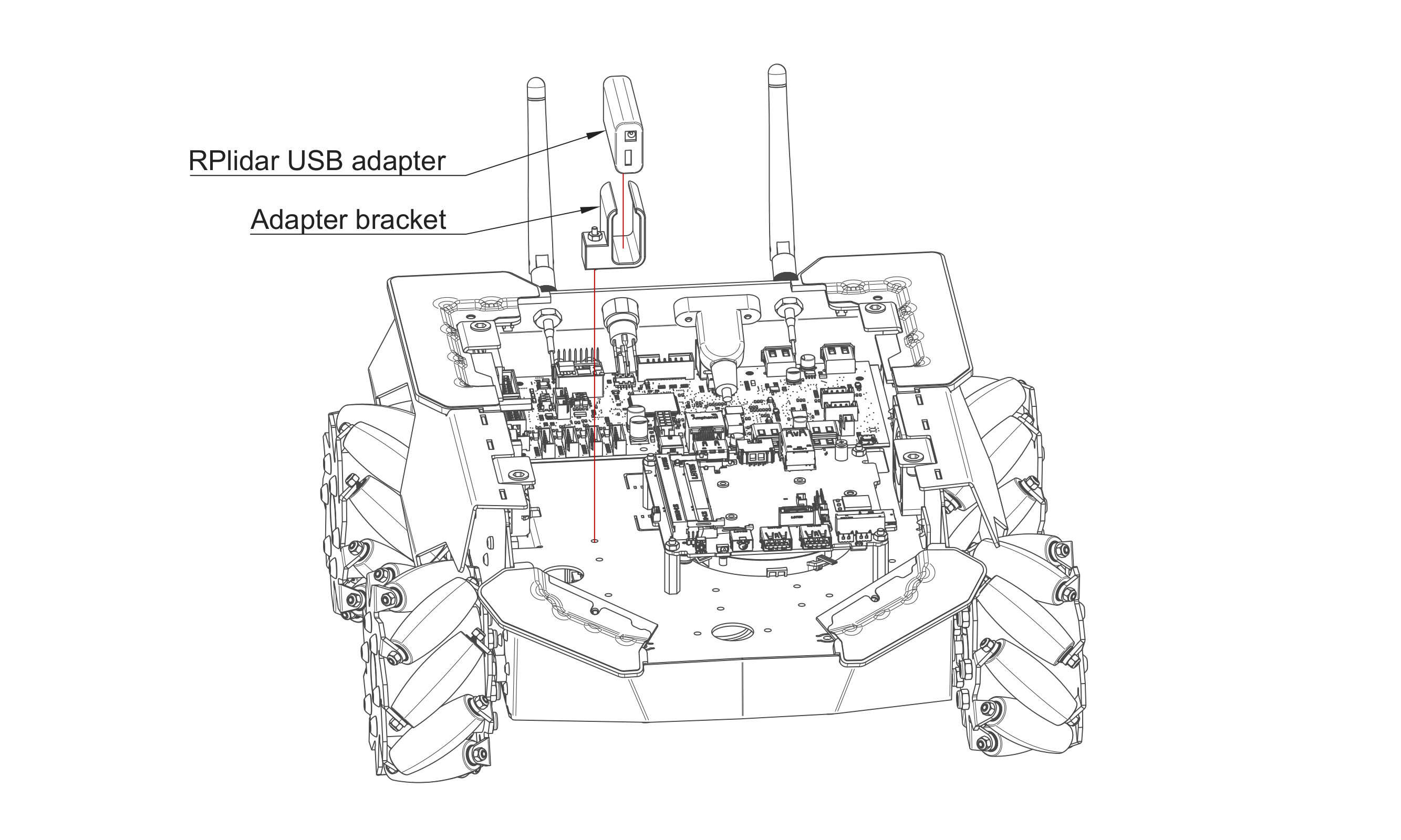
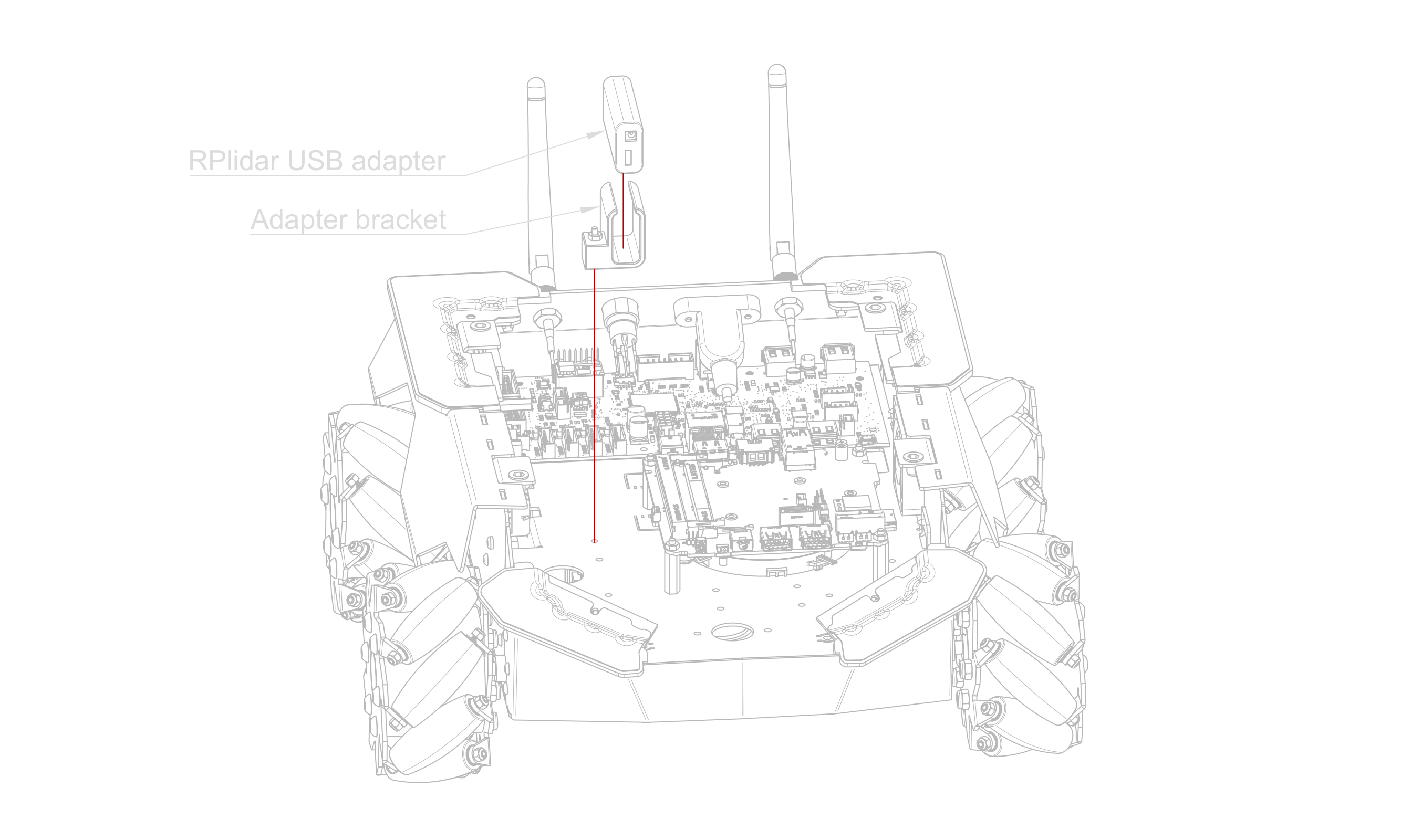
Insert the RPLIDAR USB Adapter with the Adapter Bracket into the Shelf.
-
Connect the Micro-USB to USB-A Cable between the Intel NUC and the RPLIDAR USB Adapter.
-
Connect the CABLE-X3P-380 to the Arm Board.
-
Connect the RPLIDAR S3 to the RPLIDAR USB Adapter.
-
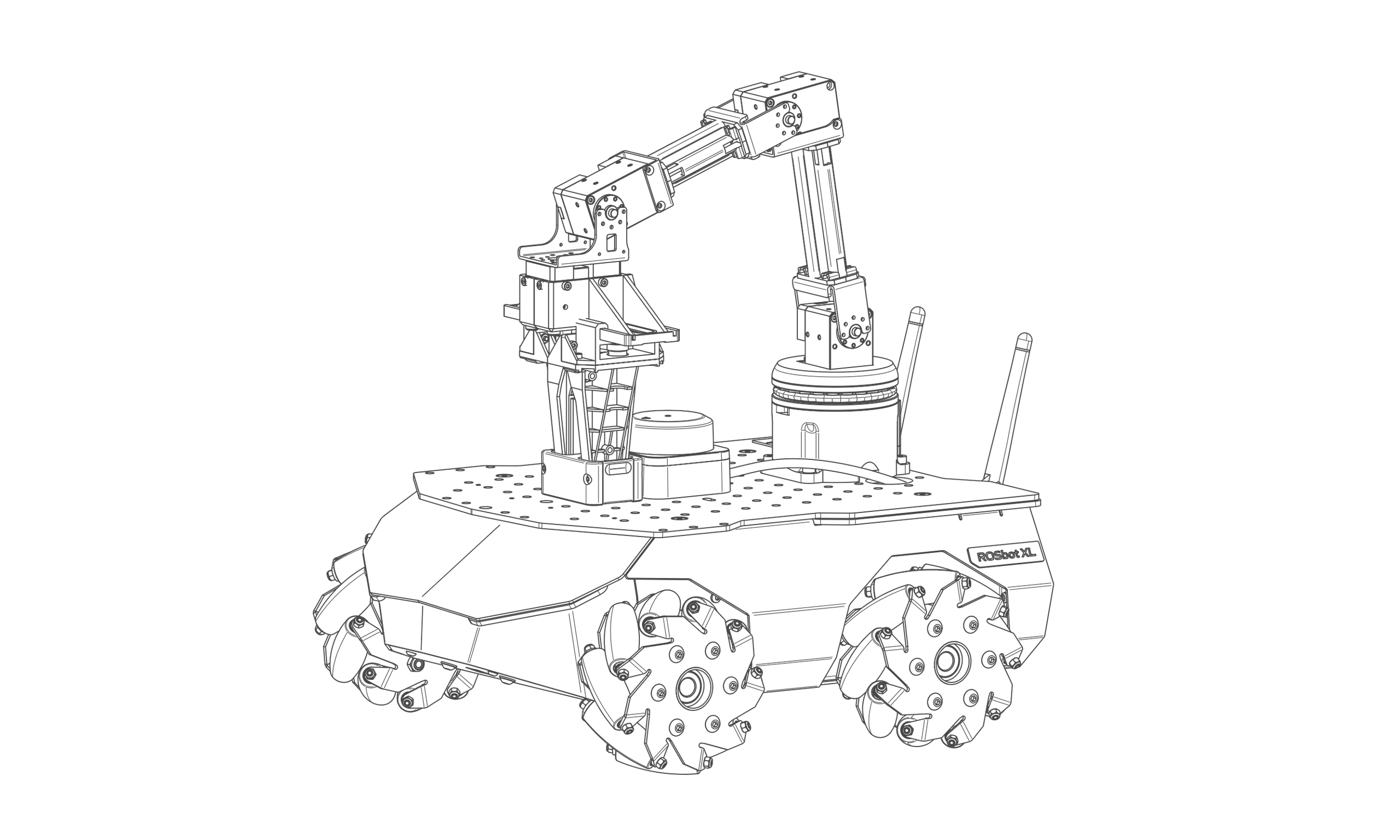
Mount the Cover on the ROSbot XL.
Software check
If the ROSbot XL Arm Board has been installed correctly, the lsusb command run on the User Computer will show the following output:
Bus 00x Device 00x: ID 0403:6014 Future Technology Devices International, Ltd FT232H Single HS USB-UART/FIFO IC
For the lidar, the output should be:
Bus 00x Device 00x: ID 10c4:ea60 Silicon Labs CP210x UART Bridge
After assembly, please refer to our OpenMANIPULATOR-X tutorial for a guide on how to run the software.
Manipulation PRO Package Assembly
This is an assembly instruction for the Husarion ROSbot XL Manipulation Pro Package.
Follow the instructions below and perform the steps in the order given.
A ROSbot XL purchased with the Manipulation Pro Package is delivered unassembled. One cardboard box contains the ROSbot XL and its standard equipment; the other contains the arm, the camera and all the components required to mount them on the robot.
To perform the steps described below, you will need basic tools such as Allen keys. These keys are supplied with the manipulator and the platform.
Assembling the arm
-
Follow the instructions provided by the arm manufacturer. Stop before step 9.
-
Slide the Top cap onto the DYNAMIXEL (ID 12) and fix it with four M2.5x8 panhead bolts.
-
Place the Thrust bearing on the DYNAMIXEL (ID 11).
-
Insert the X-SP into the bolt holes of the DYNAMIXEL (ID 12) and attach it to the FR12-S102K using FHS-M2.5x14 screws. Pay attention to the horn align marking. As shown in the image below, rotate the FR12-S102K yoke into the position given so that you can reach the bolts with a key. Then rotate it by 180° to fix the other side.
-
Connect the DYNAMIXEL (ID 12) and the DYNAMIXEL (ID 11) using the CABLE-X3P-240.
-
Slide the DYNAMIXEL (ID 11) into the Arm base. Pay attention to the cable routing inside the part and to the point where the cable leaves the housing through the notch under the bearing. Route the wires so that none of them is pinched. Fix the two parts together with four M2.5x21 countersunk bolts.
-
Continue with the manufacturer's instructions from step 10 through step 12.
-
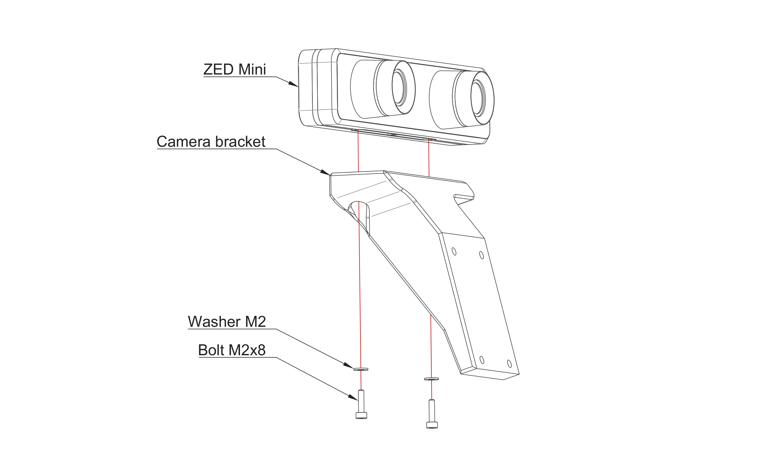
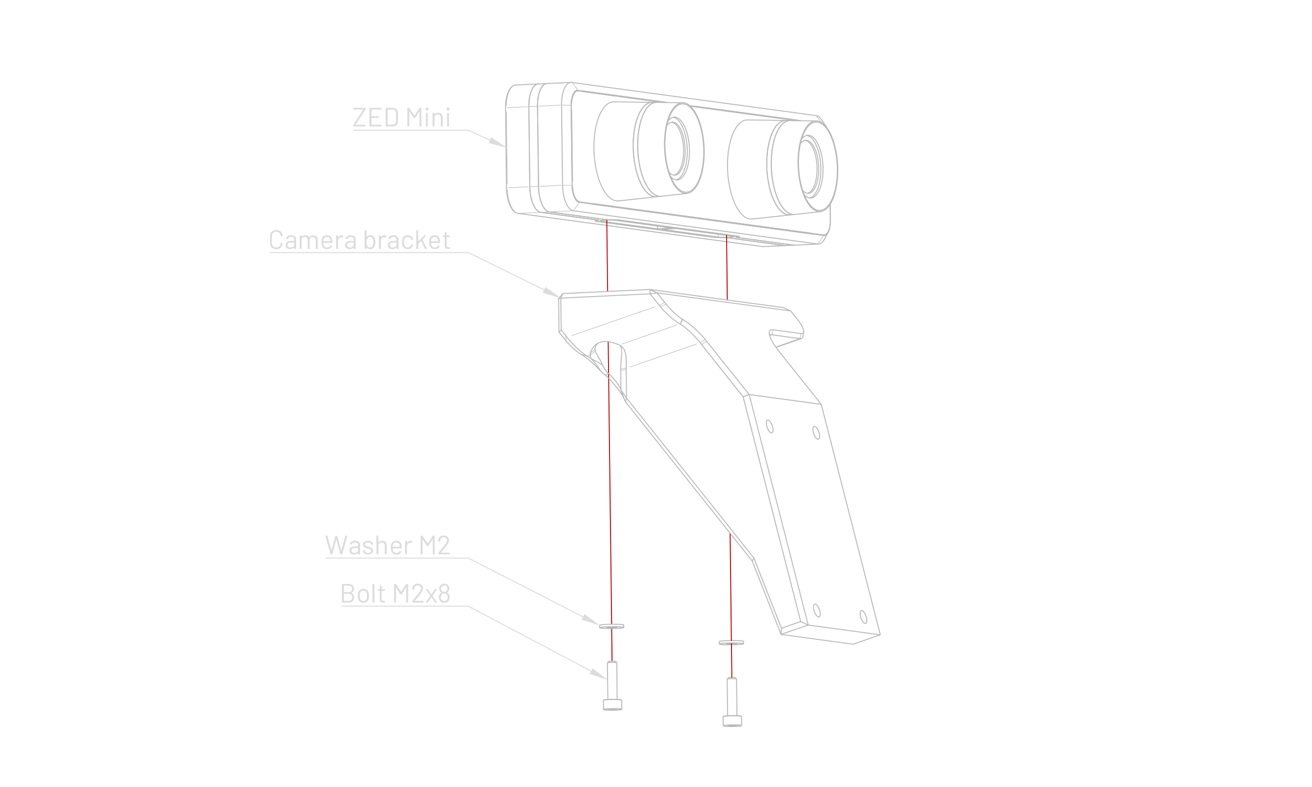
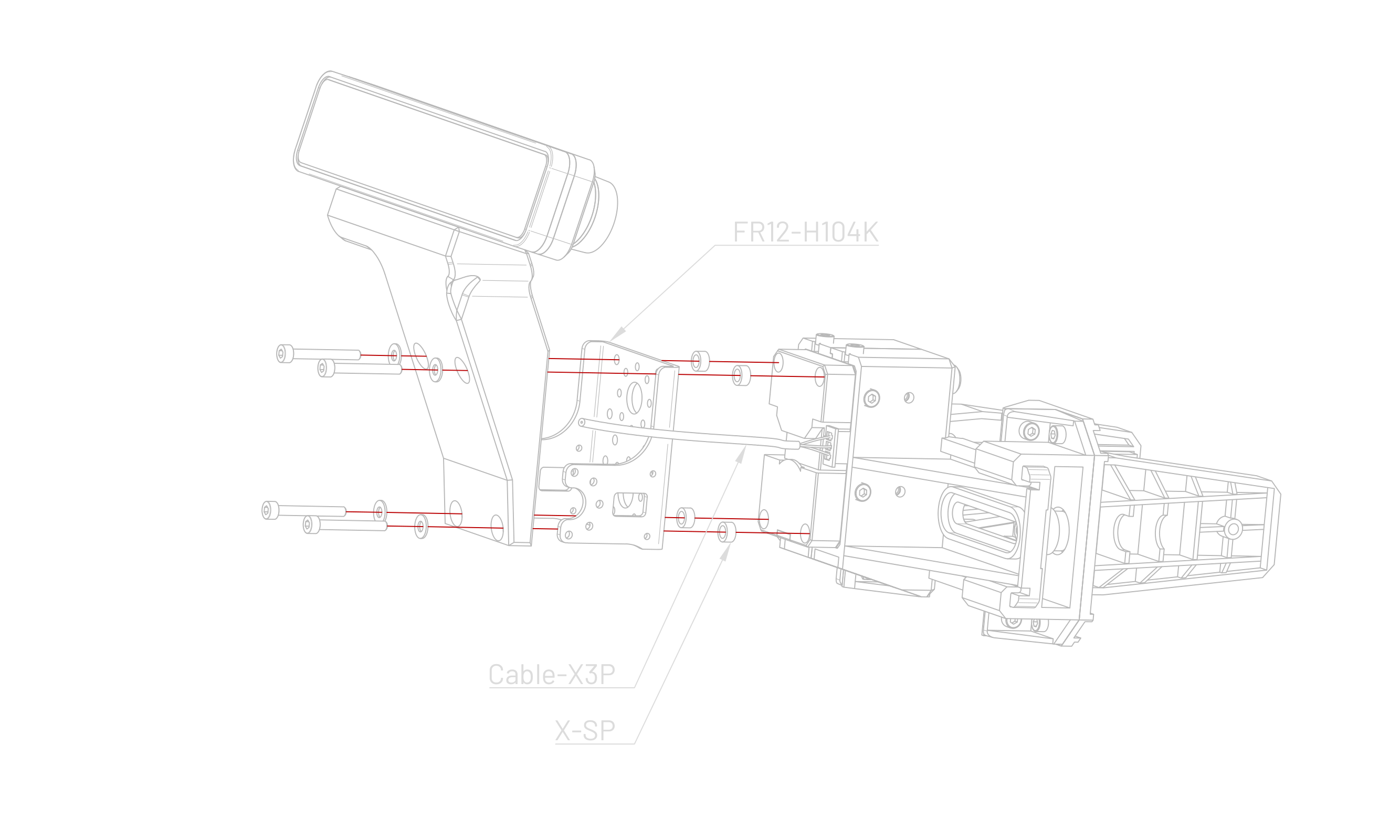
Attach the ZED Mini to the Camera Bracket.
-
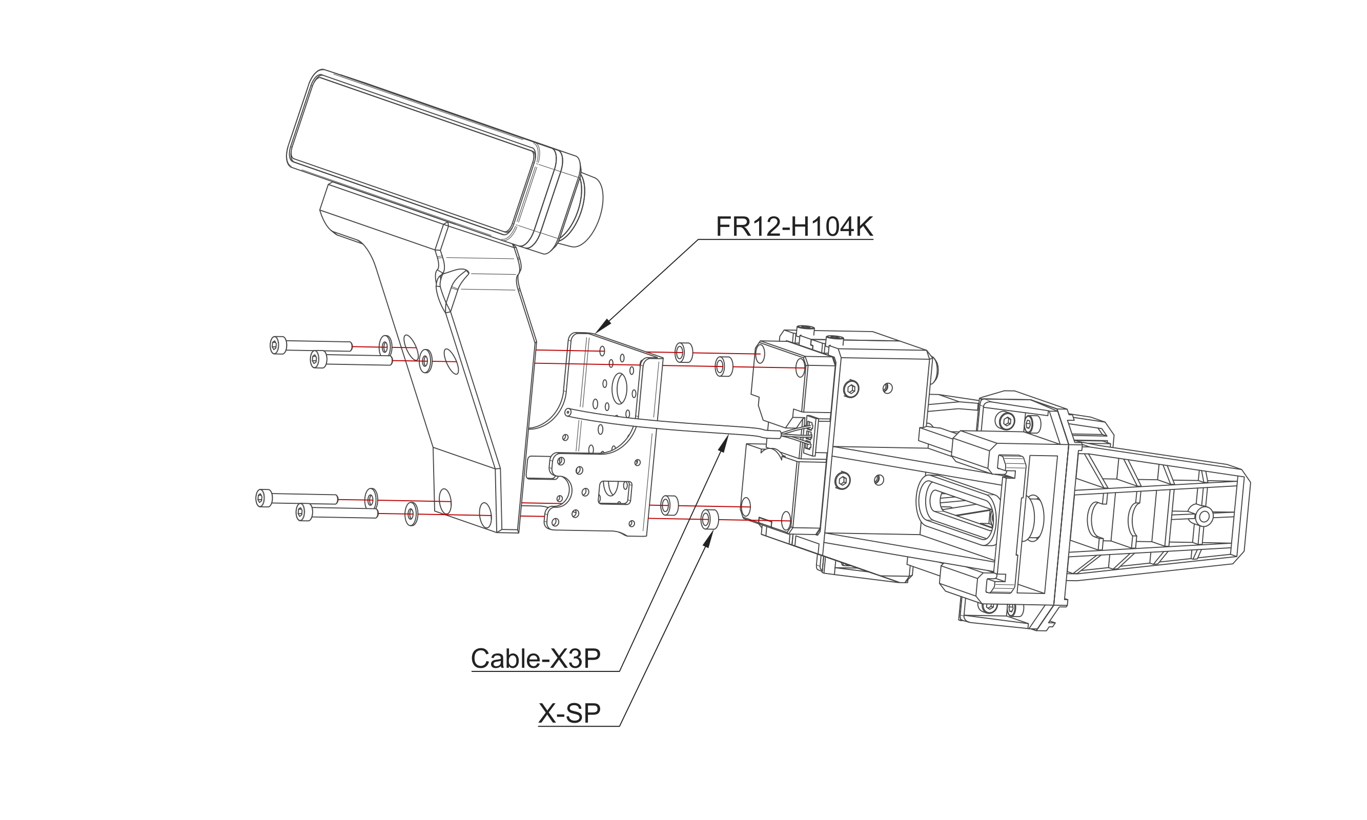
Attach the Camera Bracket to the manipulator.
-
Continue with the manufacturer's instructions from step 14.
Mounting on the ROSbot XL
- Unscrew and remove the Cover.
- Mount the Parking Bay Assembly and the Slamtec RPLIDAR S3 on the Cover.
- Connect the CABLE-X3P-380 to the DYNAMIXEL (ID 11).
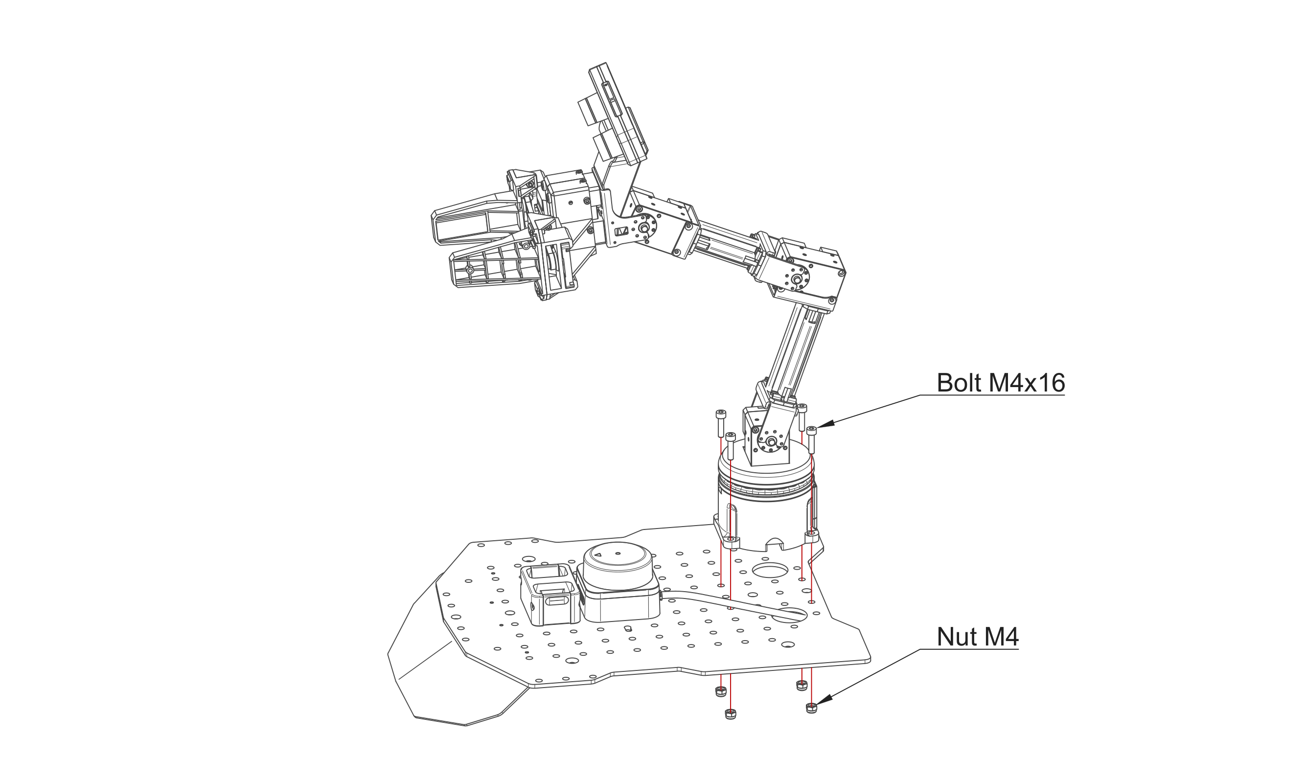
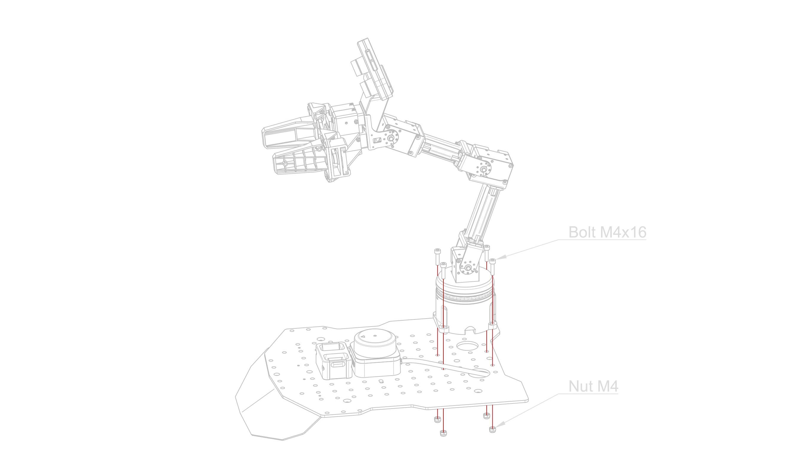
- Install the Arm base on the Cover.
- Connect the USB-C to USB-A Cable to the ZED Mini.
Depending on the production batch, some of the following steps (6 to 9) may already have been completed.
-
Connect the ROSbot XL Arm Board to the ROSbot XL Power Board and secure it with one M3x4 panhead bolt.
-
Connect the ROSbot XL Arm Board (CON1) to the ROSbot XL Digital Board (CON15) using the CABLE-JST-5-240.
-
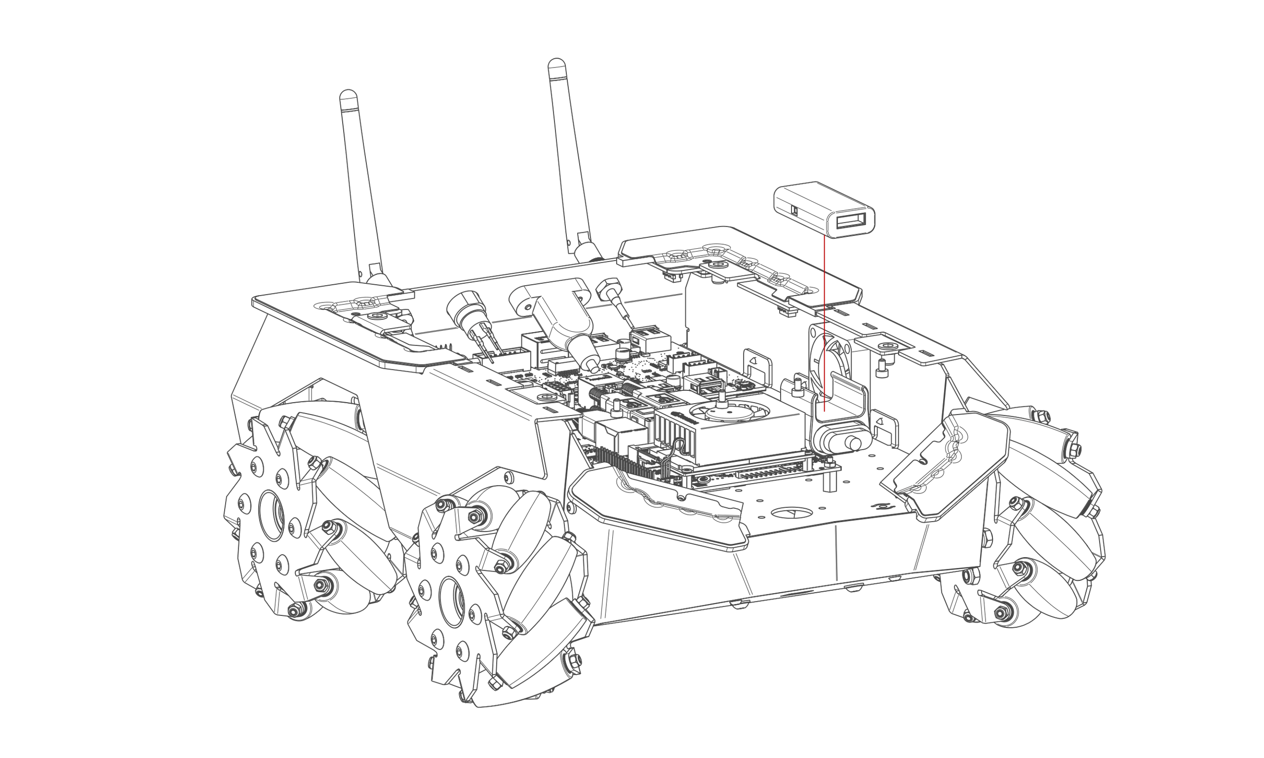
Insert the RPLIDAR USB Adapter into its mount.
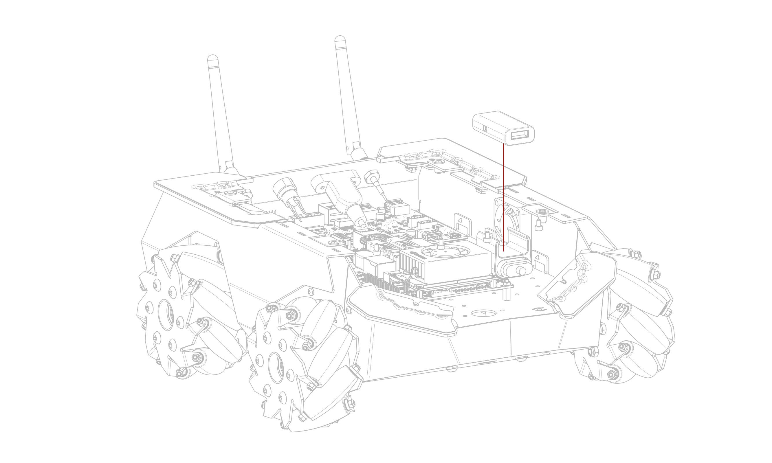
-
Connect the Micro-USB to USB-A Cable between the NVIDIA Jetson and the RPLIDAR USB Adapter.
-
Connect the CABLE-X3P-380 to the Arm Board.
-
Connect the USB-C to USB-A Cable to the NVIDIA Jetson.
-
Connect the RPLIDAR S3 to the RPLIDAR USB Adapter.
-
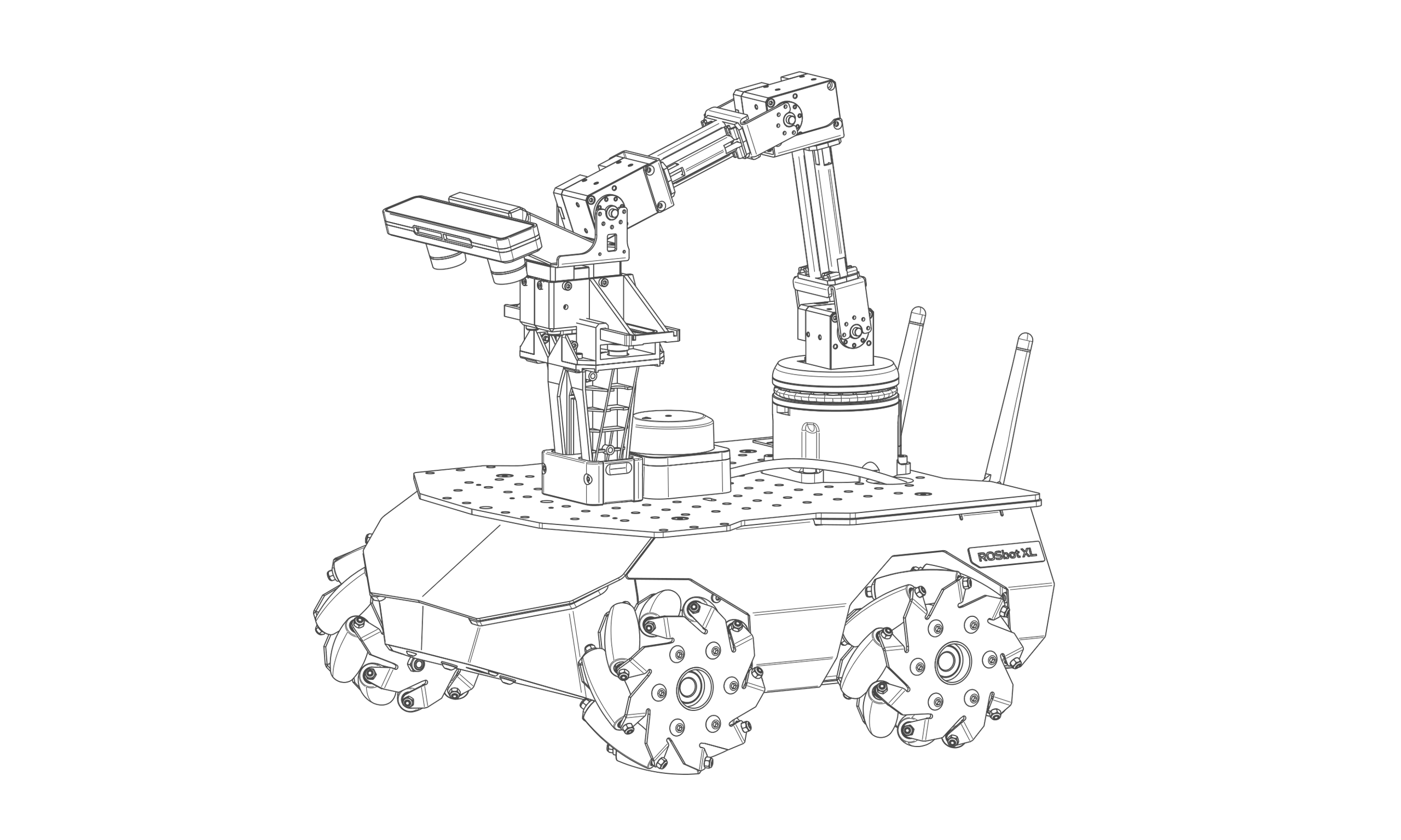
Mount the Cover on the ROSbot XL.
Software check
If the ROSbot XL Arm Board has been installed correctly, the lsusb command run on the User Computer will show the following output:
Bus 00x Device 00x: ID 0403:6014 Future Technology Devices International, Ltd FT232H Single HS USB-UART/FIFO IC
For the lidar, the output should be:
Bus 00x Device 00x: ID 10c4:ea60 Silicon Labs CP210x UART Bridge
For the ZED Mini camera, the output should be:
Bus 00x Device 00x: ID 2b03:f681 STEREOLABS ZED-M HID Interface
After assembly, please refer to our OpenMANIPULATOR-X tutorial for a guide on how to run the software.