CORE2 add-ons
CORE2brick extension kit
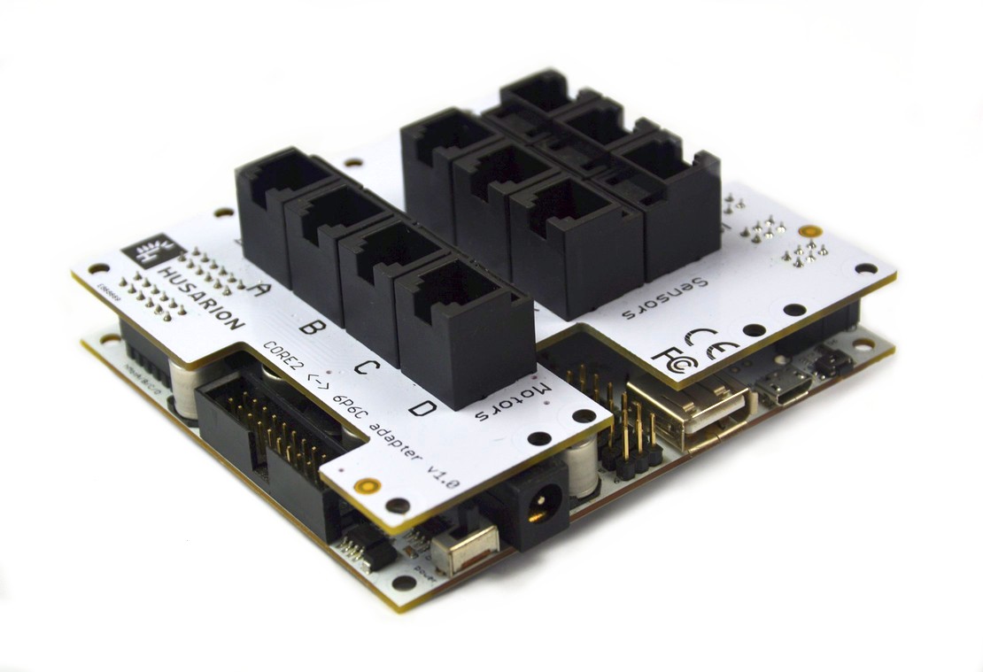
Adapter which connects CORE2 or CORE2-ROS with LEGO® Mindstorms system.
Set contains:
- A shield for CORE2 that converts on-board signals to be compatible with LEGO® Mindstorms electronic sensors (maximum 6) and motors (maximum 4).
- 10 cables (4x20 cm, 4x35 cm, 2x50 cm) to connect LEGO® sensors and motors
- hBatteryPack - a battery pack for 3x18650 Li-Ion batteries (batteries not included)
- 2 acrylic plates + set of screws, that link CORE2 and hBatteryPack with Mindstorms® mechanical parts
LEGO® Mindstorms connectors
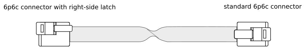
The LEGO® Mindstorms sets use non-standard, modular 6P6C connectors, also known as "modular phone jack" or "RJ connector". They are very similar to the commonly used telephone jacks, but have 6 electrical contacts and their latch is moved to the right side of the plug.
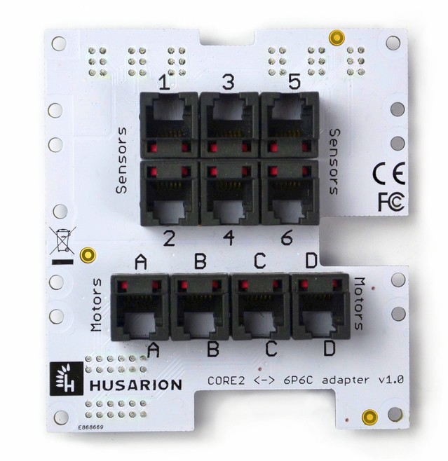
We decided to provide the shield with typical 6P6C receptacles (the crimping tool for them is widely available) and 10 cables, which are adapters in fact:
The pin numbering convention:

Motor interface
The motor interface is straight - there is 1:1 connection between CORE2 hMotor outputs and CORE2brick interface to LEGO® motors. It is just an adapter.
| CORE2 hMotor pin | CORE2 hMotor signal | 6P6C connector pin | LEGO® motor signal |
|---|---|---|---|
| 1 | H-bridge output A | 1 | Motor terminal A |
| 2 | H-bridge output B | 2 | Motor terminal B |
| 3 | GND | 3 | Neg. encoder supply |
| 4 | +5V | 4 | Pos. encoder supply |
| 5 | Encoder input A | 5 | Encoder output A |
| 6 | Encoder input B | 6 | Encoder output B |
Sensor interface
The sensor interface needs an adaptation to another pinout and signal types. The schematic describes that in the best way:
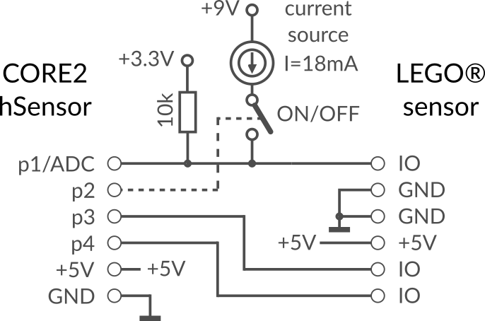
The schematic shows a single sensor interface. Each sensor connector is connected with the corresponding hSens number on CORE2, eg. hSens1 is connected with Sensor1 on the CORE2brick shield. The voltage regulators on the shield converts 5V supply from CORE2 to 3.3V and 9V, needed for LEGO® sensors. The switchable current source is necessary for some sensors.
| CORE2 hSensor pin | CORE2 hSensor signal | 6P6C connector pin | LEGO® sensor signal |
|---|---|---|---|
| 1 | GPIO / ADC / interrupt | 1 | GPIO / ADC / current source |
| 2 | GPIO | - | switches the current source on pin 1, active with high level |
| 3 | GPIO/SCL/TX* | 5 | GPIO/SCL/RX* |
| 4 | GPIO/SDA/RX* | 6 | GPIO/SDA/TX* |
| 5 | +5V output | 4 | +5V input |
| 6 | GND | 2,3 | GND |
*- see hSensor description for the specific functions availability
hBatteryPack
The same which is used in Telepresence robot, ROSbot and CORE2block kit. Full description here: hBatteryPack
Acrylic plates and screws
There are 2 transparent, PMMA plates with holes. The hole spacing is 8mm to make them compatible with LEGO® Mindstorms mechanics.
The bigger board is prepared for assembling with CORE2, using M3x6 standoffs, M3x10 screws to connect standoffs with PMMA board and M3x4 screws to attach CORE2 PCB.
The smaller board is prepared for assembling with hBatteryPack, using M3x6 standoffs, M3x10 screws to connect standoffs with PMMA board and M3x4 screws to attach hBatteryPack PCB.
CORE2block extension kit
Adapter which connects CORE2 or CORE2-ROS with Makeblock system.
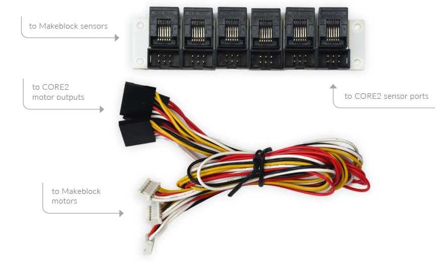
The main part are adapters for sensors and motors. Electrical interface of Makeblock sensors is similar to CORE2 hSensor, but some pin-swapping is needed. These adapters do the job.
Set contains:
- 6 cables and adapters for connecting Makeblock sensors to the Husarion CORE2 controller (6x 15cm)
- 4 cables for connecting Makeblock DC motors (with encoder) to the Husarion CORE2 controller (4x 30cm)
- 2 cables for connecting Makeblock DC motors (without encoder) to the Husarion CORE2 controller (2x 30cm)
- hBatteryPack - a battery pack for 3x18650 Li-Ion batteries (batteries not included)
- 2 acrylic plates + set of screws, that link CORE2 and hBatteryPack with Makeblock mechanical parts
Sensor adapter
Sensor adapters consist of:
- 6 PCB's which connects to CORE2 from one side, and to the Makeblock sensors from the other side.
- 6 ribbon cables to connect CORE2 hSensors with adapter PCBs.
The connectors used with CORE2 are shrouded box headers: 2×3-Pin, 0.1" (2.54 mm), male, mating with IDC 0.50" pitch ribbon cables. We use Amphenol T821106A1S100CEU or compatible. On the "Makeblock side" a 6P6C sockets are used to work with 6P6C crimped connectors, similar to the telephone jacks. In the Makeblock documentation they are called "RJ25". We use Molex 95501-2661 or compatible.
Adapter PCBs that can be separated by breaking them off, if you like. The connections on each adapter are explained on the circuit diagram below:
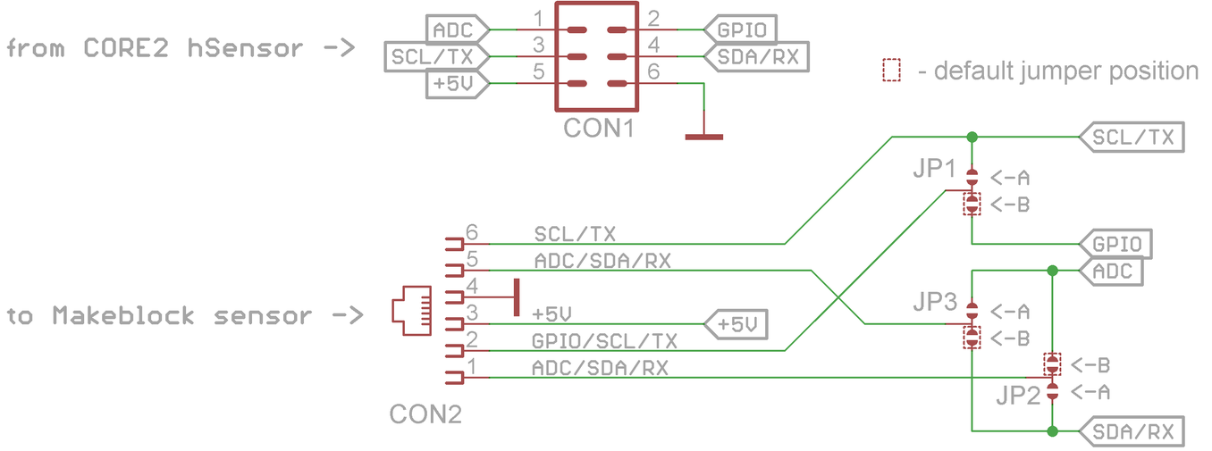
Important: the Makeblock documentation shows a different, non-standard pin order for 6P6C (RJ25) connector. We follow the order used by Molex and FCI connector manufacturers, and also by LEGO® in their Mindstorms kits.
On the bottom side of PCB you can find jumpers for configuring the adapter connections. They are needed for interfacing CORE2 with different Makeblock sensors. The photo below shows the jumper position on PCB:
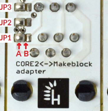
And this table should be helpful for you:
| Makeblock sensor name | Main interface | CORE2 hSens port no | JP1-JP3 position |
|---|---|---|---|
| Me Compass | I2C | 1 or 2 | B |
| Me Ultrasonic Sensor | digital/interrupt | 1-6 | B |
| Me 3-Axis Accelerometer and Gyro Sensor | I2C | 1 or 2 | B |
| Me 7-Segment Serial Display | 2-wire serial | 3-4 | A |
| Me Bluetooth Module(Dual Mode) | UART | 3 or 4 | A |
| Me Flame Sensor | digital | 1-6 | A or B |
| Me Line Follower | digital | 1-6 | B |
| Me Light Sensor | analog | 1-6 | B |
| Me Infrared Receiver Decode | I2C | 1-6 | A or B |
| Me PM2.5 Sensor | UART | 3 or 4 | A |
| Me Potentiometer | analog | 1-6 | B |
| Me PIR Motion Sensor | digital/interrupt | 1-6 | B |
| Me RGB LED | serial | 3 or 4 | A or B |
| Me-Shutter | digital | 1-6 | A or B |
| Me Slide Potentiometer | analog | 1-6 | B |
| Me USB Host | serial | 3 or 4 | A |
| Me Touch Sensor | digital | 1-6 | A or B |
| Me Temperature and Humidity Sensor | digital | 1-6 | A or B |
| Me Sound Sensor | analog | 1-6 | B |
| Me TFT LCD Screen – 2.2 Inch | UART | 3 or 4 | A |
| Me Line Follower Array | UART | 1-6 | B |
Motor adapter
A simple, 6-wire cable with different connectors on both sides:
- On the CORE2 side, there is a black, 6-pin, female, wire-to-board connector with 2.54mm pitch.
- On the Makeblock motor side, there is a similar connector, but white, with 2mm pitch and polarization keys.
Black connectors:
- Harwin M20-1060600 housing with Harwin M20-1160046 crimp contacts
- Molex 50-57-9006 (70066-0005) housing with Molex 0016020xxx 70058 crimp contacts
- Amphenol (former FCI) 65039-031LF housing with 47649-000LF or 47565-002LF crimp contacts
- TE connectivity 104439-5 housing with 181270-1 crimp contacts And many other manufacturers. These connectors are commonly known as "Dupont".
White connectors:
- JST PHR-6 housing with SPH-001T-P0.5S crimp contacts There are also other manufacturers.
Caution! The cable doesn't have any polarization key on the black connector. Please make sure that you connect it in correct orientation.
The motor adapter allows to use the following Makeblock motors:
- DC Motor-25 9V/700RPM
- DC Motor-37 12V/200RPM
- DC Motor-37 12V/50RPM
- 36 DC Geared Motor 12V 240RPM
- Mini Metal Gear Motor – N20 DC 12V
- DC Encoder Motor – 25 6V/185RPM
- 180 Optical Encoder Motor
- Optical Encoder Motor-25 9V/185RPM
- Optical Encoder Motor-25 9V/86RPM
Of course, if you can deal with soldering custom connectors, you will be able to use other motors as well.
hBatteryPack
The same which is used in Telepresence robot, ROSbot and CORE2brick kit. Full description here: hBatteryPack
Acrylic plates and screws
There are 2 transparent, PMMA plates with holes. The hole spacing is 8mm to make them compatible with Makeblock mechanics.
The bigger board is prepared for assembling with CORE2, using M3x6 standoffs, M3x10 screws to connect standoffs with PMMA board and M3x4 screws to attach CORE2 PCB.
The smaller board is prepared for assembling with hBatteryPack, using M3x6 standoffs, M3x10 screws to connect standoffs with PMMA board and M3x4 screws to attach hBatteryPack PCB.
Servo controller for CORE2
Allows to connect 12 additional servos to CORE2.
Communicates with CORE2 via hSensor interface. Up to four servo controllers can work on one hSensor port thanks to 2-bit addressing. The step down DC/DC converter with software-controlled output voltage is available on board to simplify power connections - you can supply the servo controller and CORE2 from the same power source.
Servo controller can deliver up to 3A average current to the servos.
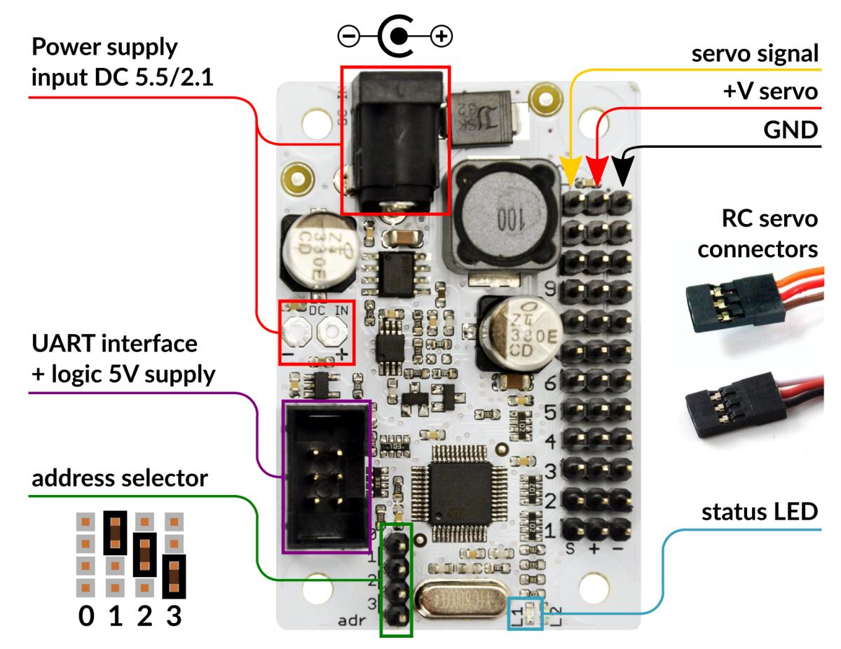
The picture below describes the pinout of the Servo driver.
First run
Connect the Vin voltage (+6V...+16V) and servos that you need. Connect the UART interface to hSens3 or hSens4 on CORE2 using the flat IDC cable. Build your program for CORE2 following the example available here
A library for ServoDriver is available on GitHub: https://github.com/husarion/modules
Specification
- Integrated DC/DC converter
- Output voltage (+V servo) selectable by software: 5V / 6V / 7.4V / 8.6V
- 12 PWM outputs, 3.3V logic level, compatible with most analog and digital RC servos
- 3A nominal output current
- 5A peak output current
- Input voltage range (Vin): 6...16V
- Logic supply voltage: +5V typical, +4...+10V is acceptable.
- Overcurrent and short-circuit protection
Address selection
You can connect up to four servo controllers to one UART interface (hSens3 or hSens4 port of CORE2) in parallel. The IDC flat cable allows to crimp additional connectors anywhere along the cable. Each command sent by CORE2 to servo controller contains an address from 0 to 3. Each servo controller will execute only the commands that match the local address, configured with jumper. The default address is 0 (without jumper).
LED behavior
In the current firmware, the LED is turned on if both power supplies (+5V and +Vin) are connected. LED is blinking when servo controller receives commands.
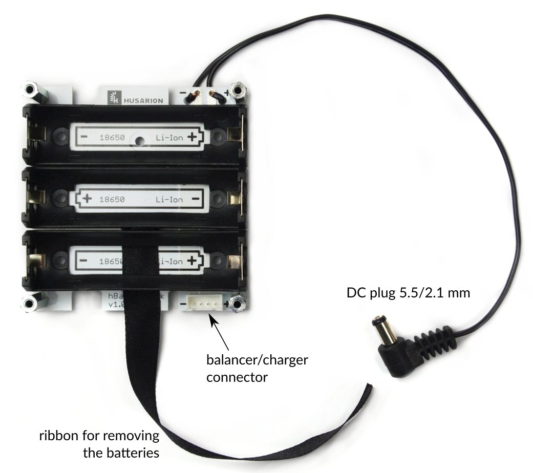
hBatteryPack kit
A common part for:
Keeps your 18650 cells together and delivers the sum of their voltage to your CORE2 or other device :)
Compatible batteries
hBatteryPack is compatible with all 18650 Li-Ion cells but only the "protected" ones (with an internal protection circuits) can be used. There are two main reasons:
- Safety - a protection from a short-circuit condition is essential,
- Size - the batteries with protection circuit are a little longer than bare Li-Ion cells, therefore they fit better to the holders and the electrical contact is more reliable.
The image below shows four batteries. Counting from the top, there is:
- black - the battery with protection circuit; it's longer than others and have a protruding tip, like a popular AA batteries, that provides a good electrical contact in the battery holder,
- yellow - this cell one doesn't have a protection circuit and is short,
- blue - this one has a visible tip on the left; it's a cheap battery sold as the battery with protection, but it doesn't have one for sure,
- pink - again the cell without a protection circuit.
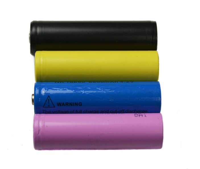
We strongly recommend using the first type with the protection circuit and the tip on the '+' side.
Balancer/charger connector
The connector type used in hBatteryPack for charging is well-known in a community of RC model makers. It's a 4-pin JST XH connector. The pinout is typical.
Optional acrylic plate
The optional perforated, acrylic board can be used to connect the battery pack to LEGO® bricks or other mechanics:
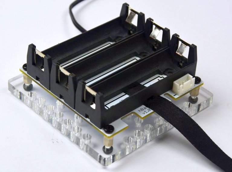
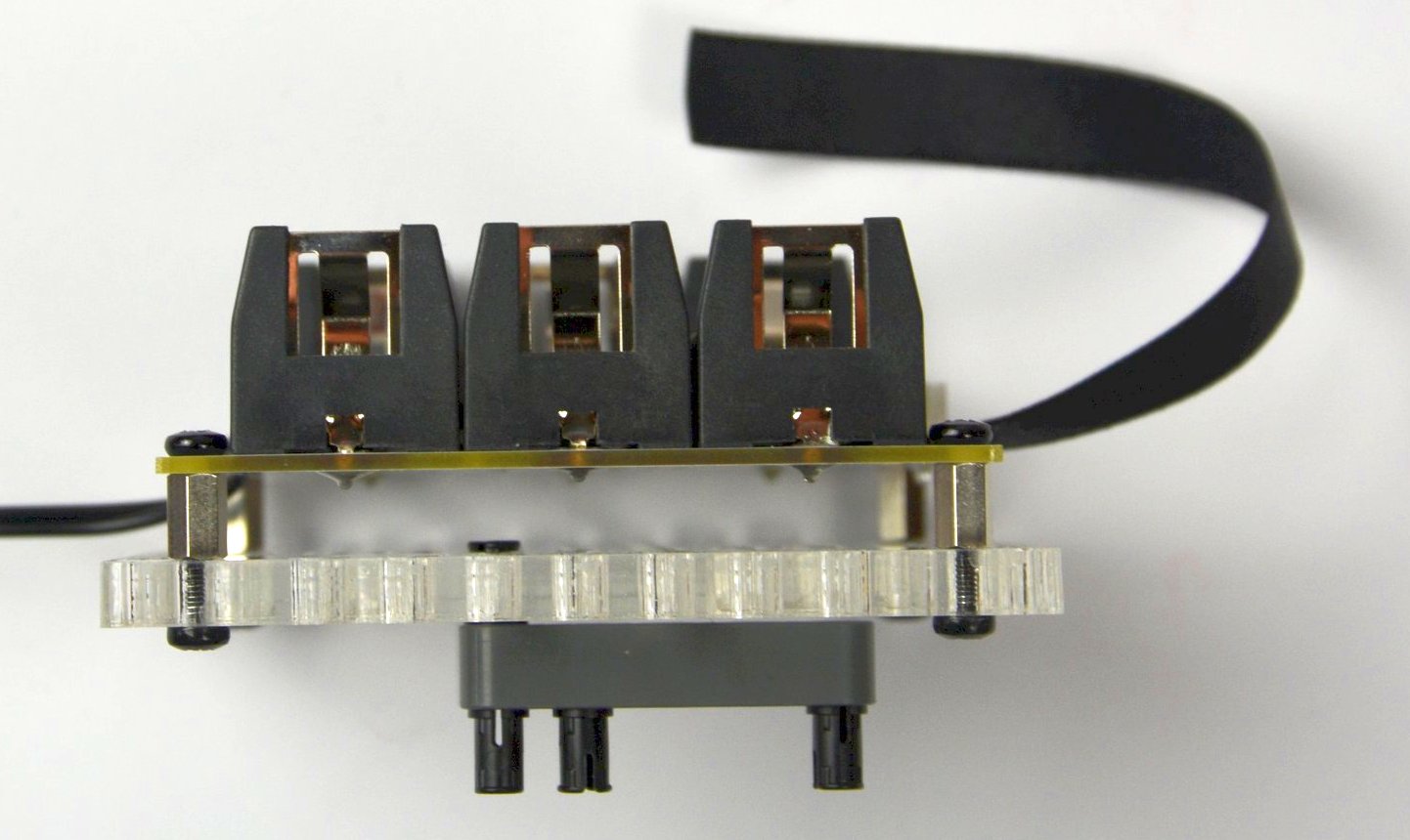
The acrylic plate is prepared for assembling with hBatteryPack using M3x6 standoffs, M3x10 screws to connect standoffs with plate and M3x4 screws to attach hBatteryPack PCB.