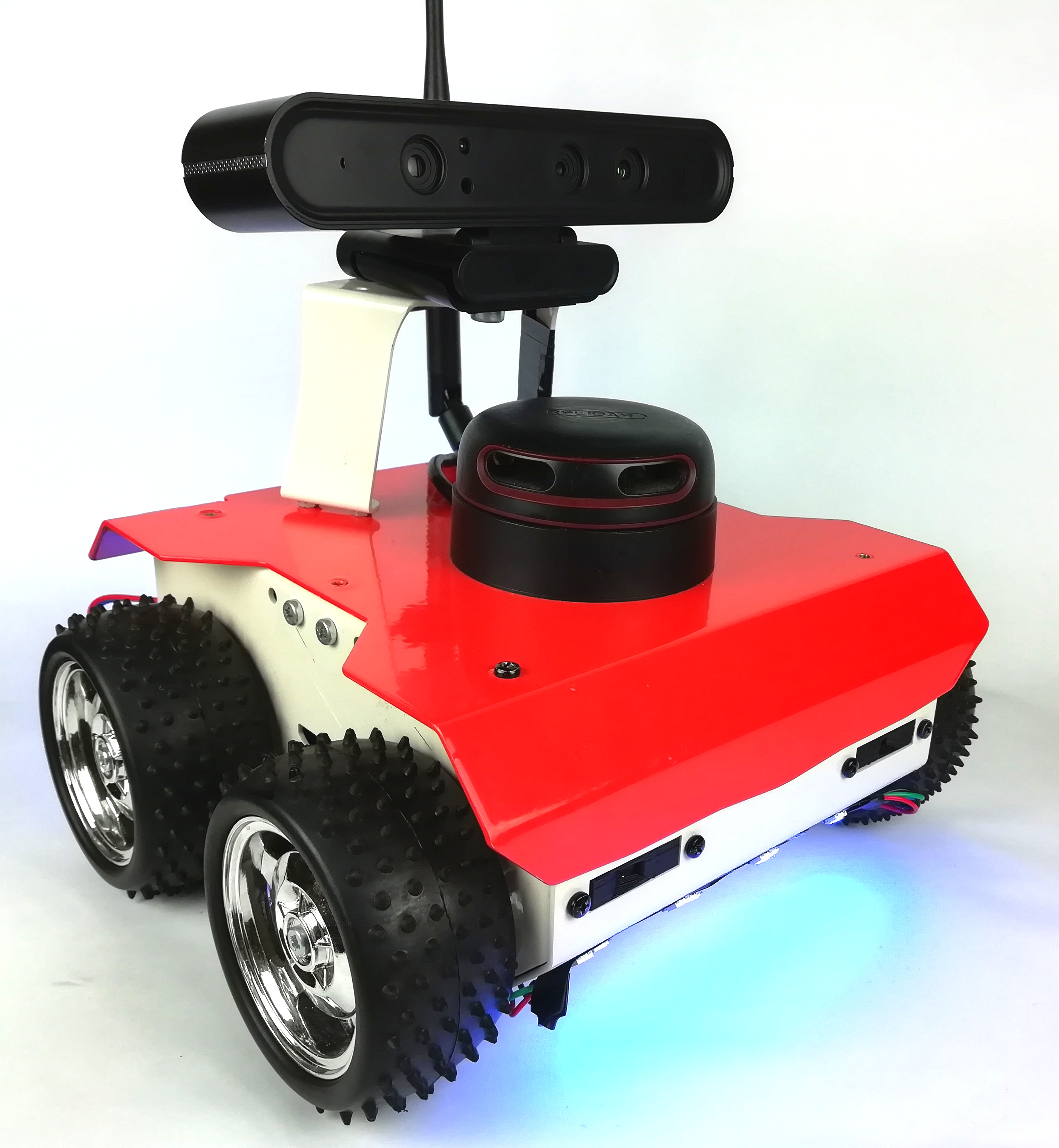
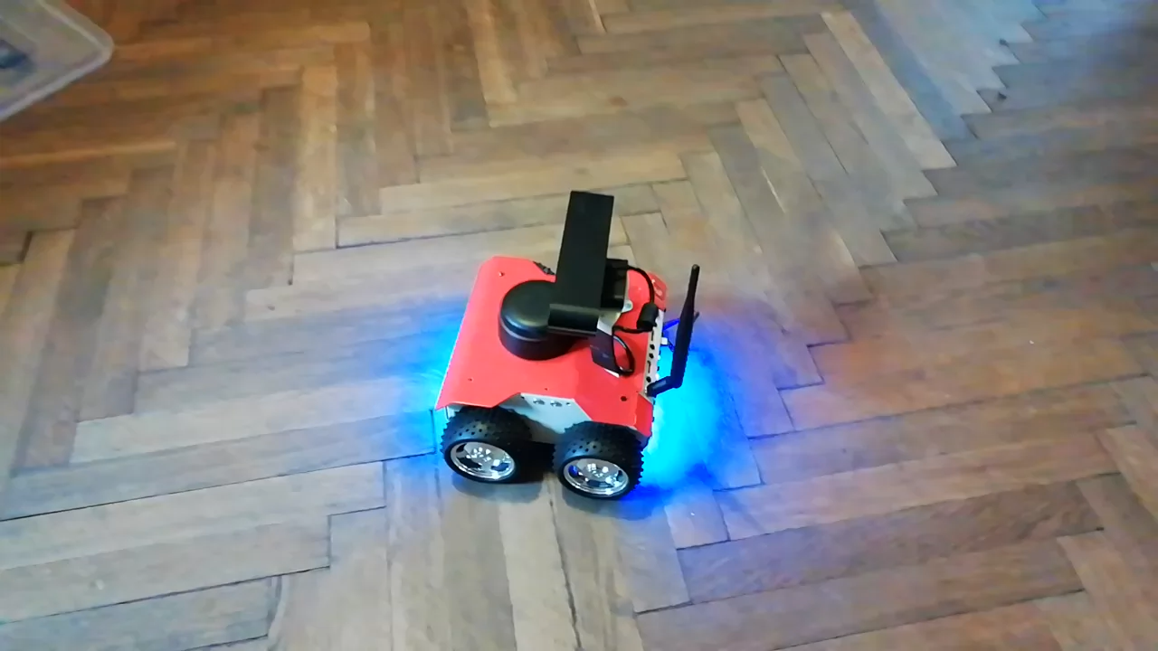
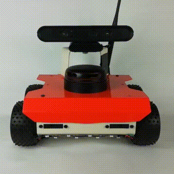
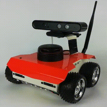
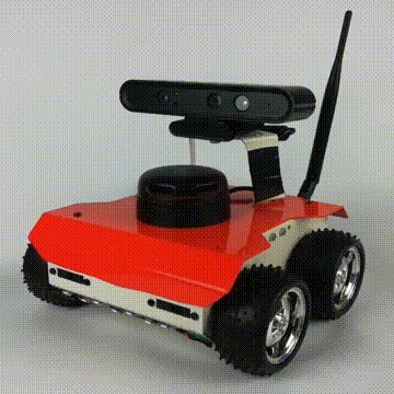
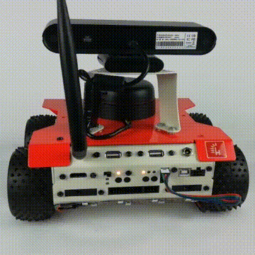
ROSbot with WS2812B LEDs signalization
Introduction
By default ROSbot has three LEDs that can be used by user's applications to indicate status and battery condition. However, their location at the rear panel and the fact that they have only single color can limit possible use cases. In more demanding applications where there are many distinct robot's states we need more clear, visible and robust solution.
In this tutorial we will present you with elegant and easy approach to this problem. We will use a popular and cheap ws2812b RGB LED strip. Each LED pixel is individually addressed and it is capable of displaying 256 levels of brightness for each color giving overall 16 millions of color depth. The ws2812b IC utilizes the NZR protocol with 800Kbit/s speed which allows high refresh rates. Using these LEDs we can achieve a clear ROSbot's visual state indication.
Prerequisites
Hardware
Additionally to ROSbot, basic soldering skills and soldering equipment you will need following items and tools:
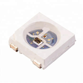
- WS2812b LED strip 1m 30leds/pixels/m - we will use only 16 pixels, but you can use more. However, these leds are quite power hungry and they can significantly reduce ROSbot's operation time if used in large quantities (they consume 52.5 mA max per pixel).

- scissors
- electric wire stripper
- double sided tape
- single-core cable - three colors
- heat shrink sleeves to protect connections between cut led strips
- 2.54mm (0.1") Pitch Female Connector 3 Position - to swap with the default connector that comes with the strip
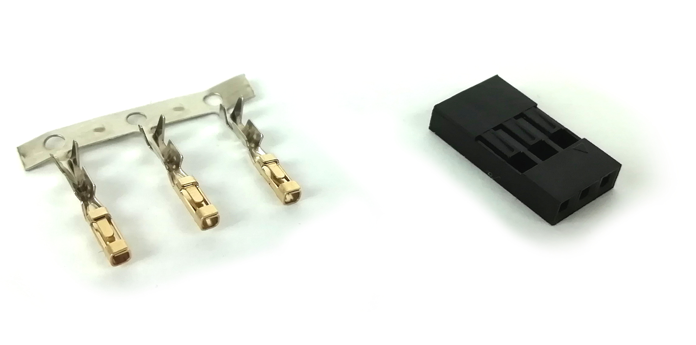
- crimping pliers or universal pliers - to attach crimp pins
Software
This tutorial uses the new firmware for ROSbot, based on Mbed OS system. To learn more about the new firmware please get familiar with the firmware's GitHub page.
We recommend you to check our Using CORE2 with Mbed OS tutorial. It will introduce you to the Mbed OS environment and tools.
Building from source
To prepare the environment, build and upload the firmware please follow the instructions from the README file.
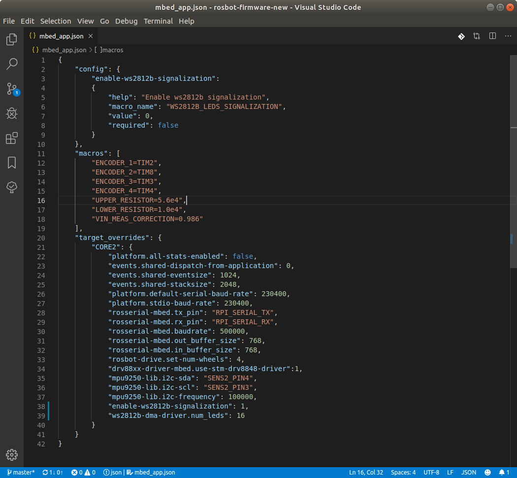
Before building the code, find mbed_app.json file in your project and enable the ws2812b driver by changing the line:
"enable-ws2812b-signalization": 0
to:
"enable-ws2812b-signalization": 1
If you intend to use more then 16 led pixels (which is the value hardcoded in the firmware) you can easily change that by adding a new line:
"ws2812b-dma-driver.num_leds": x
where x is the number of leds you want to use.
Build firmware using BUILD (RELEASE) task. The firmware.bin file should appear in the directory BUILD/RELEASE. To upload the firmware using stm32loader please follow the guide from previous tutorial.
Ready to use firmware packages
If you don't want to go through the procedures above, we prepared for you .bin files ready to be uploaded to your ROSbot. They have following settings:
- ws2812b driver is enabled by default
- number of led pixels is set to 16
- rosserial baudrate is set to:
500000for ROSbot 2.0460800for ROSbot 2.0 Pro
Use stm32loader to upload the firmware. Please follow the guide from previous tutorial.
Downloads:
LED strip installation
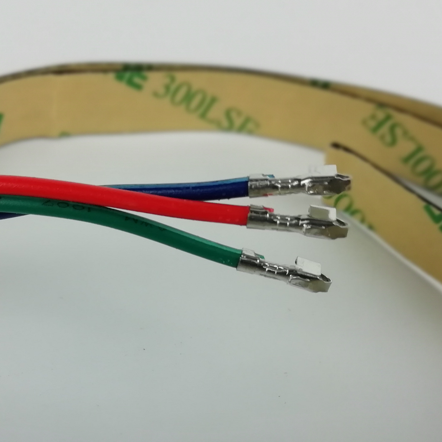
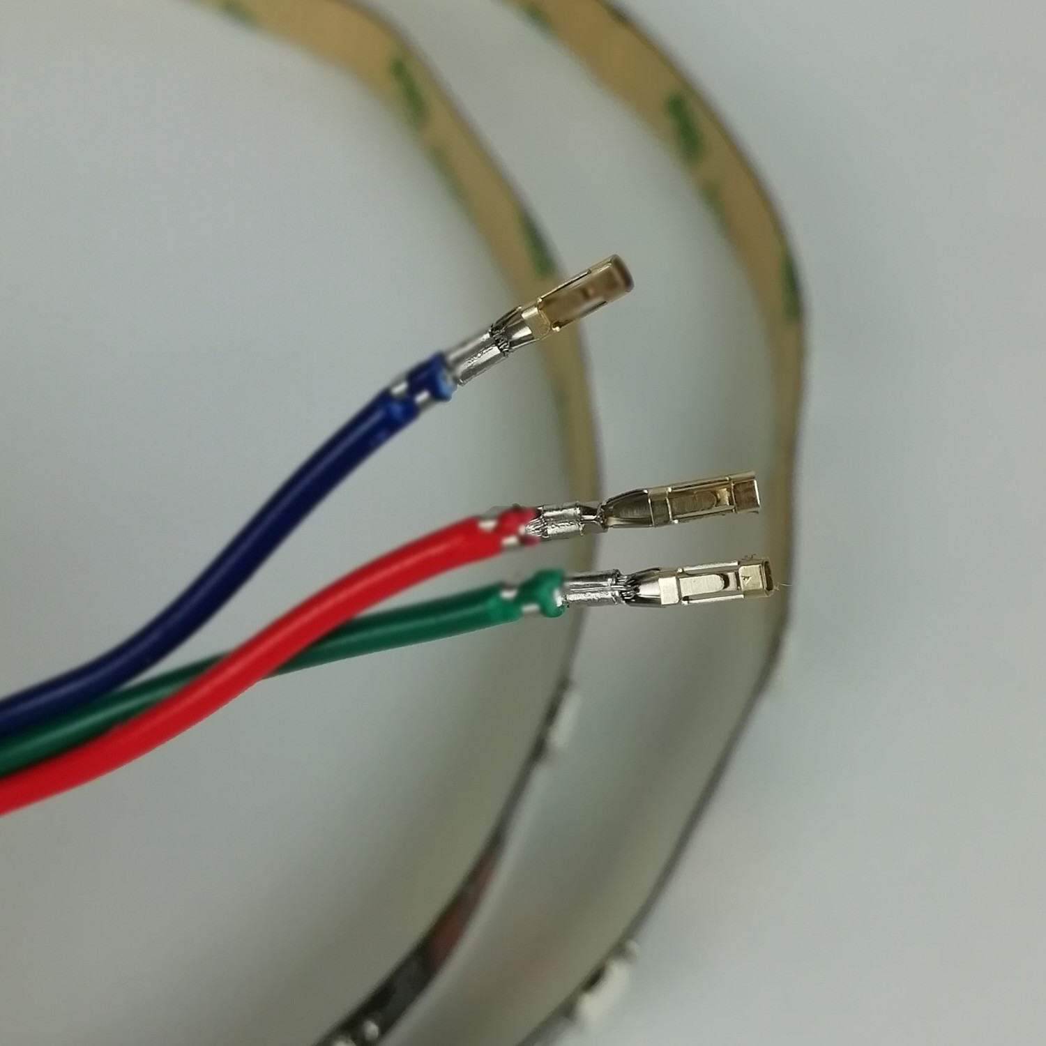
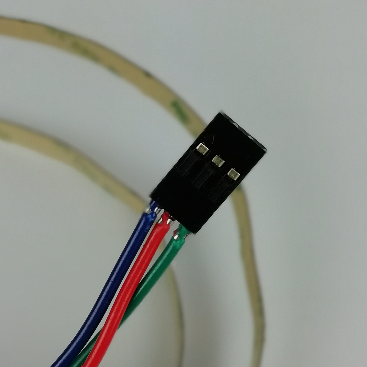
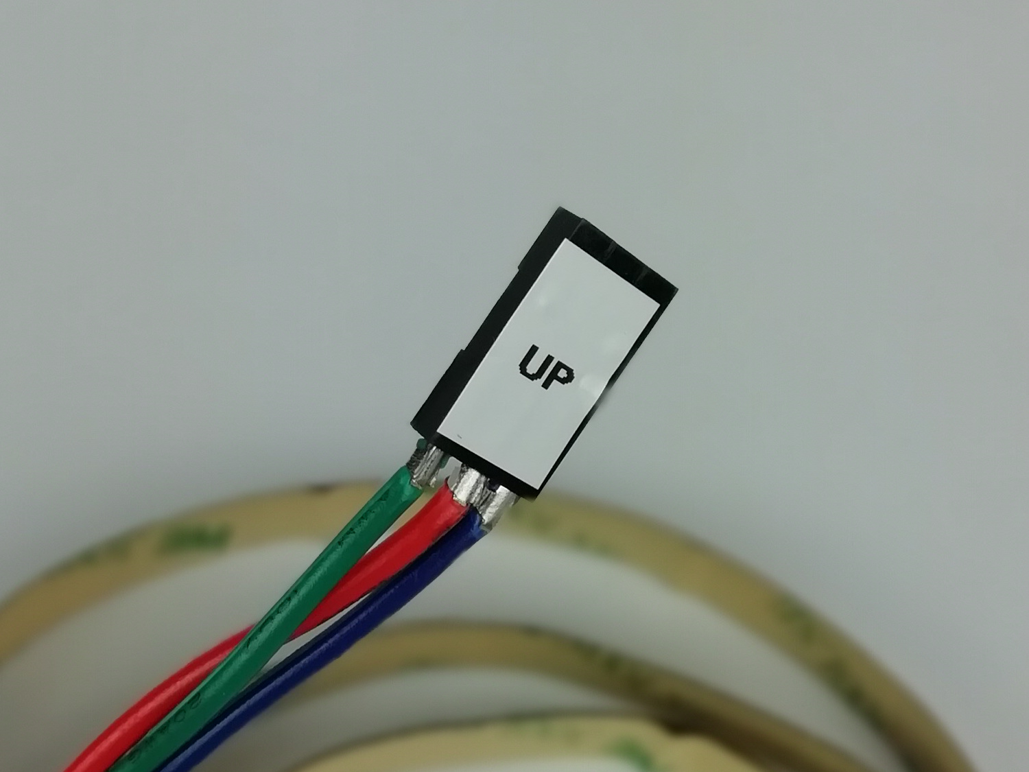
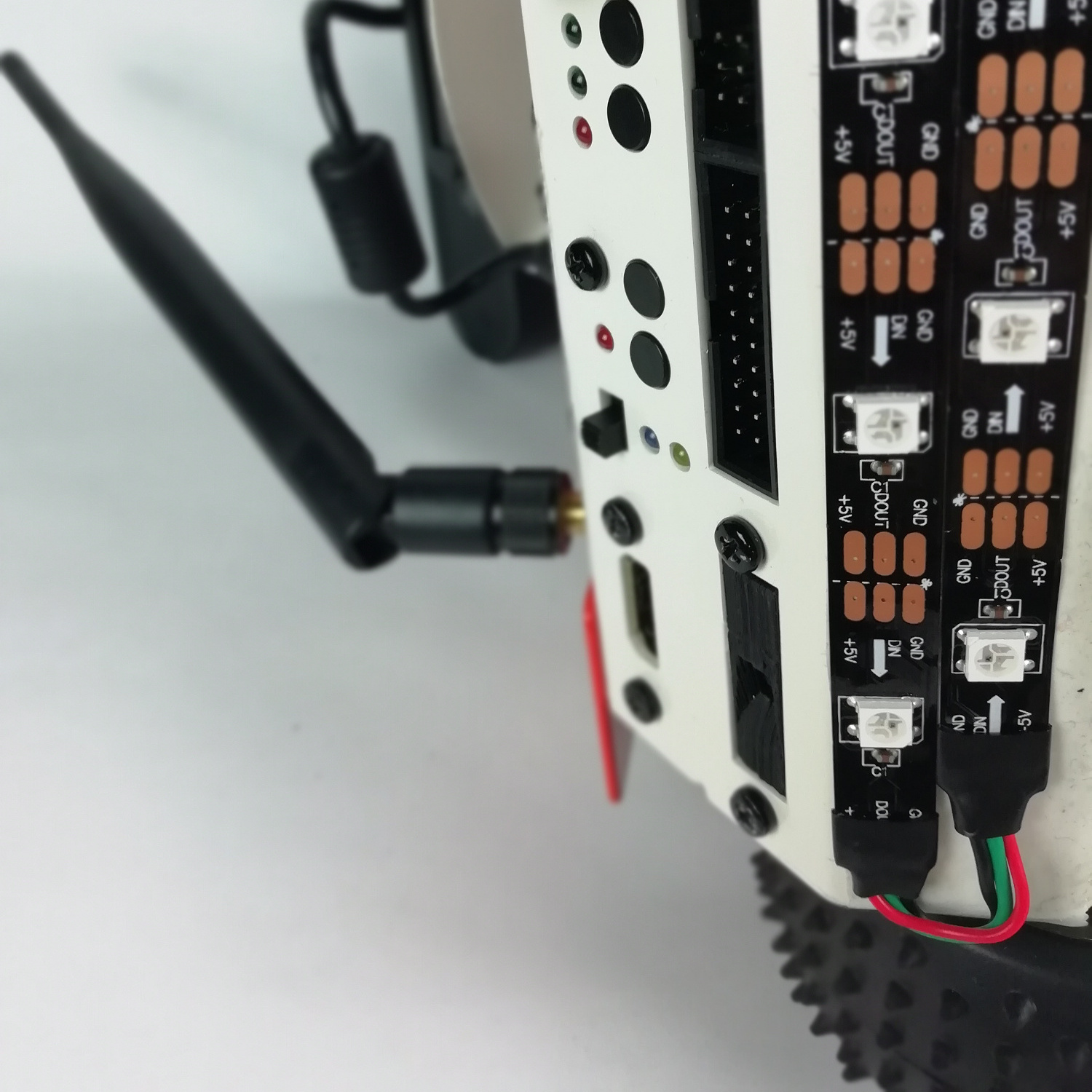
1. Install the new connector.First thing you have to do is to install pin crimps for the new connector. I used a crimp pliers, but you can also attach them using a standard pliers. It might be a little bit more difficult though.
| 1 | 2 |
|---|---|
 |  |
| 3 | 4 |
|---|---|
 |  |
| 5 | |
|---|---|
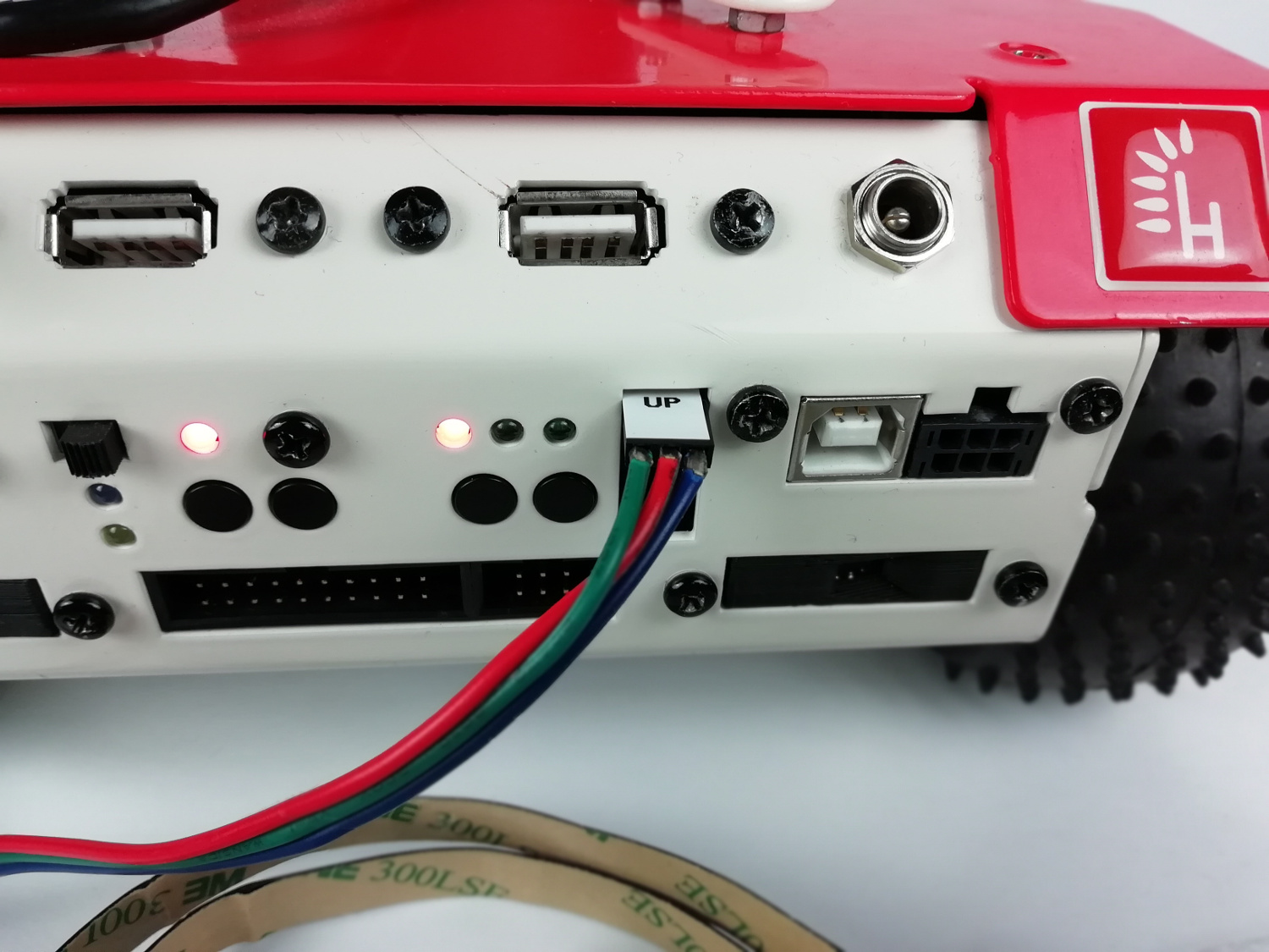 |
It is a good practice to color code your connectors, in this case to mark the connector polarity. I used a label printer to label an "up" of the connector, but a piece of color tape should be enough.
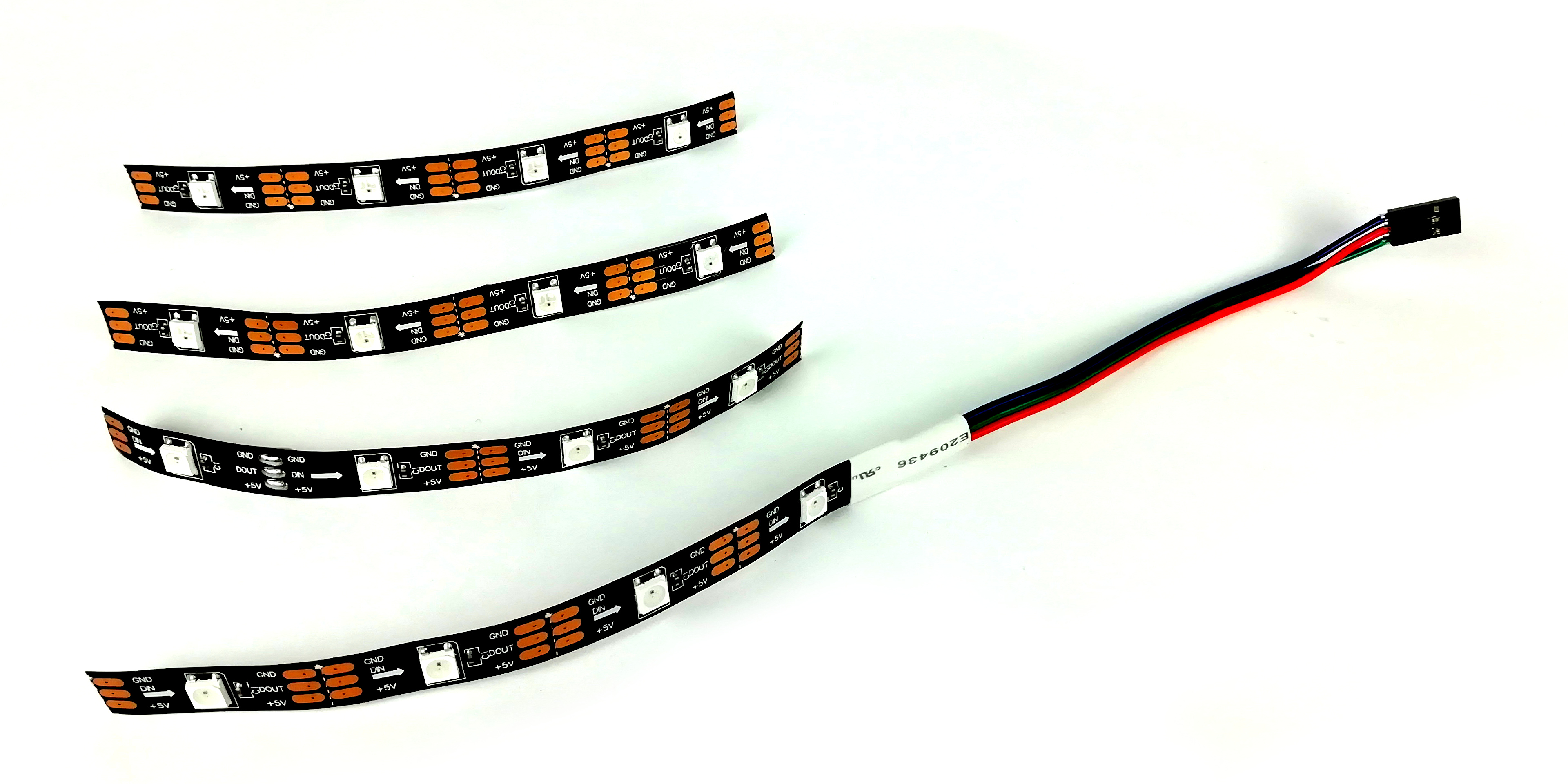
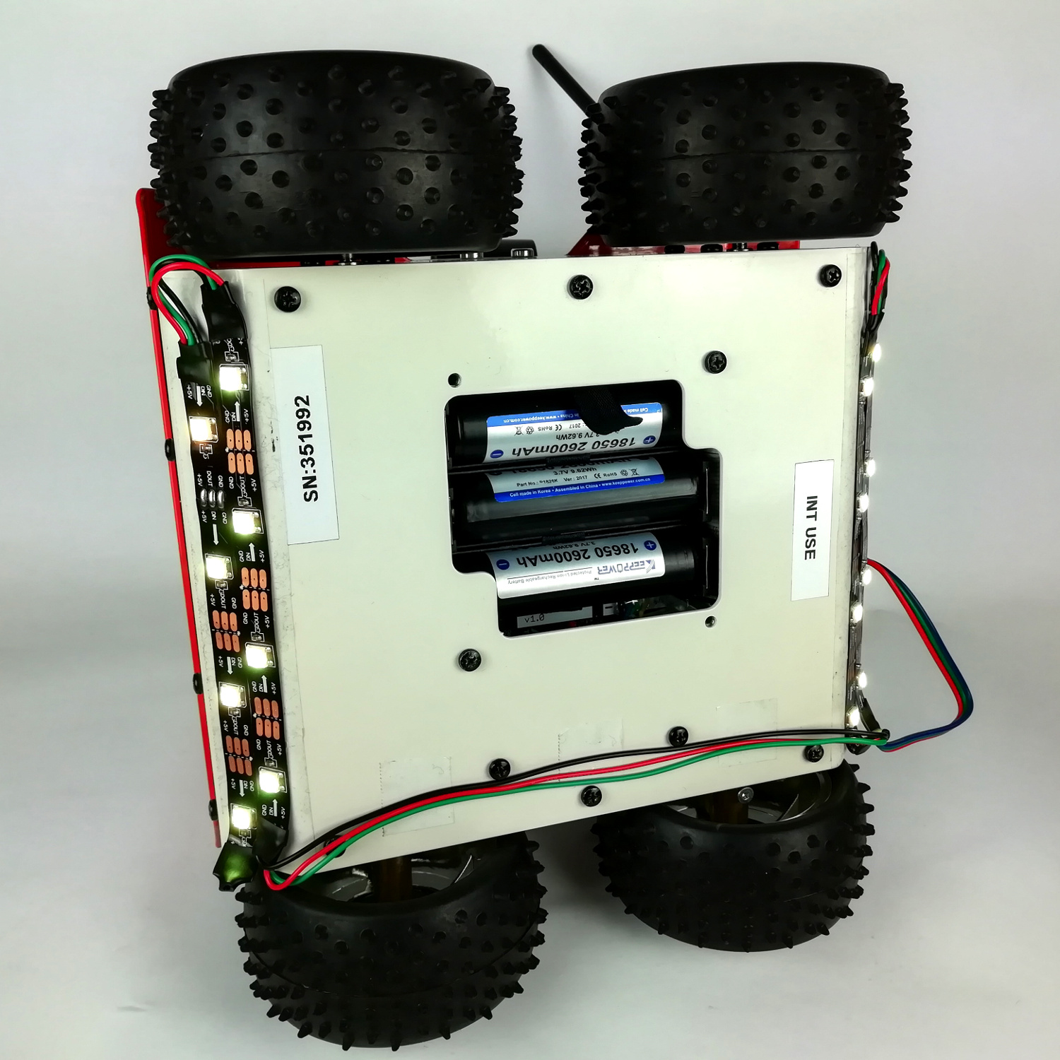
2. Prepare led strips.I recommend to place your led installation in "chamfers" under front and rear panel of ROSbot's body. This way illumination will be clearly visible but it won't be irritating for eyes. In each "chamfer" we can fit 2 strips, 4 pixels each. You should prepare 4 pieces:
It is not necessary since the strips usually come with its own adhesive.
Here is the connection diagram:
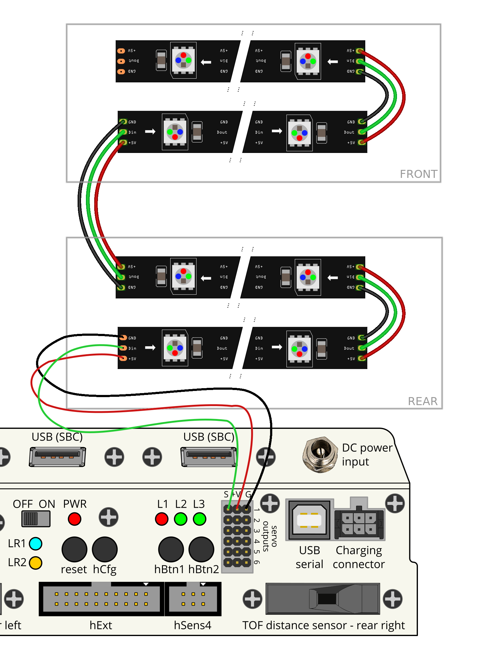
Measure the distance between each strip to prepare enough cable and install the heat shrinking sleeves before soldering. Remember to connect the DOUT port of one strip with the DIN port of an another strip, otherwise they won't work. After you have the whole installation prepared you can attach it to ROSbot using provided adhesive or the double sided tape.
Using the new functionality
Required ROS packages
Before we start make sure you have the rosbot_ekf package installed on your device. The package contains the EKF and custom messages used by the new firmware. It is required for the new firmware to work correctly. The package also contains example nodes used further in this tutorial.
The package is located HERE. Clone the package to your ROSbot's ros_ws/src directory.
Following dependencies are also required. On your device please run:
sudo apt-get install ros-kinetic-robot-localization
Now you can compile the rosbot_ekf package. In your ros_ws directory run catkin_make.
Using rosbot_ekf package
To start the rosserial communication and EKF run:
roslaunch rosbot_ekf all.launch
For PRO version add parameter:
roslaunch rosbot_ekf all.launch rosbot_pro:=true
You can also include this launch in your custom launch files using:
<include file="$(find rosbot_ekf)/launch/all.launch"/>
For PRO version it will look like that:
<include file="$(find rosbot_ekf)/launch/all.launch">
    <arg name="rosbot_pro" value="true"/>
</include>
WS2812B animations interface in ROS
The new firmware provides a service server /config with the custom message type rosbot_ekf/Configuration.
rossrv show rosbot_ekf/Configuration
string command
string data
---
uint8 SUCCESS=0
uint8 FAILURE=1
uint8 COMMAND_NOT_FOUND=2
string data
uint8 result
The WS2812B animations are accessible via SANI command. For most commands there are two arguments. First is the animation letter and second is the color of animation. Here is an example for setting a red fading animation:
rosservice call /config "command: `SANI`
>data: 'F #aa0000'"
Available commands:
O- OFFS <hex color code>- SOLID COLORF <hex color code>- FADE IN FADE OUT ANIMATIONB <hex color code>- BLINK FRONT/REAR ANIMATIONR- RAINBOW ANIMATION
cmd_vel example
In this example we will use the ws2812b leds to achieve a different ROSbot illumination depending on the robot's speed. The result is really cool. Check it out:
To access the effect, firstly launch a rosbot_ekf all.launch:
roslaunch rosbot_ekf all.launch
PRO:
roslaunch rosbot_ekf all.launch rosbot_pro=true
After that you need to run the example node:
rosrun rosbot_ekf cmd_vel_ws2812b_example
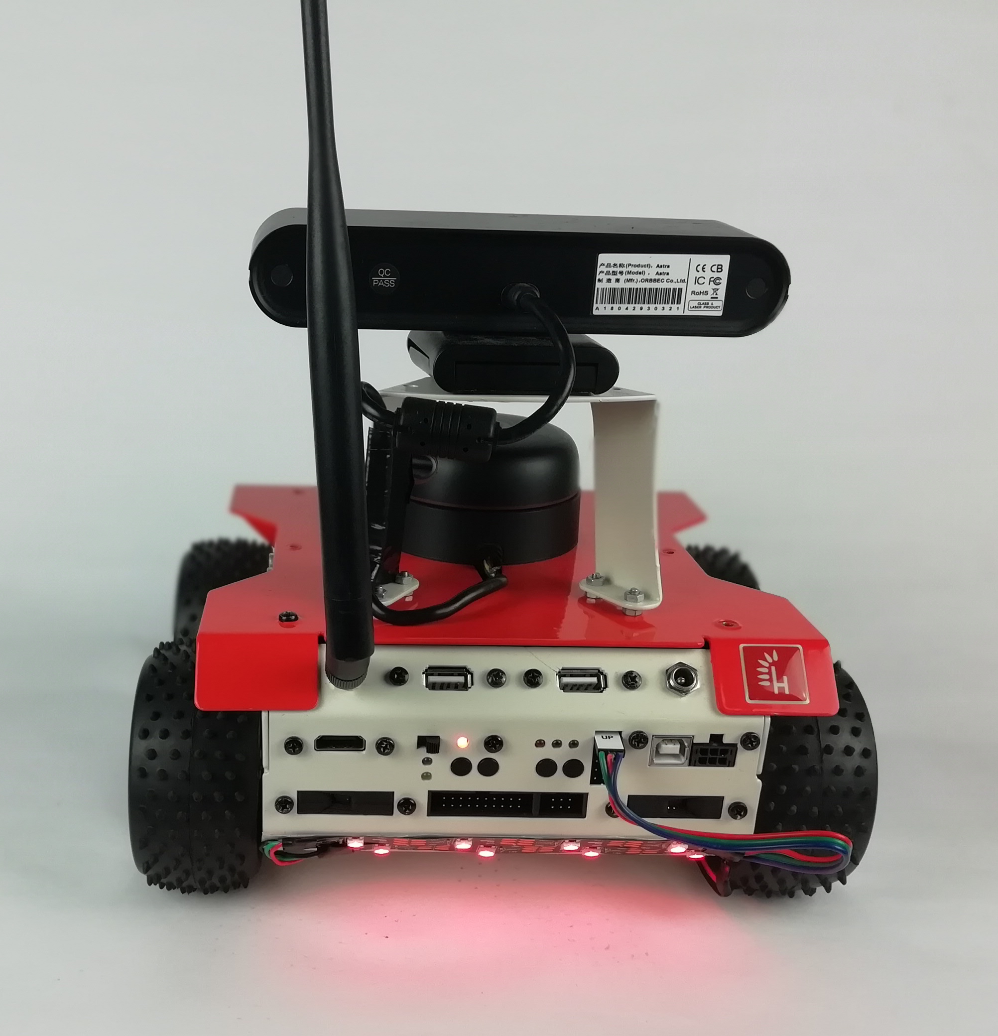
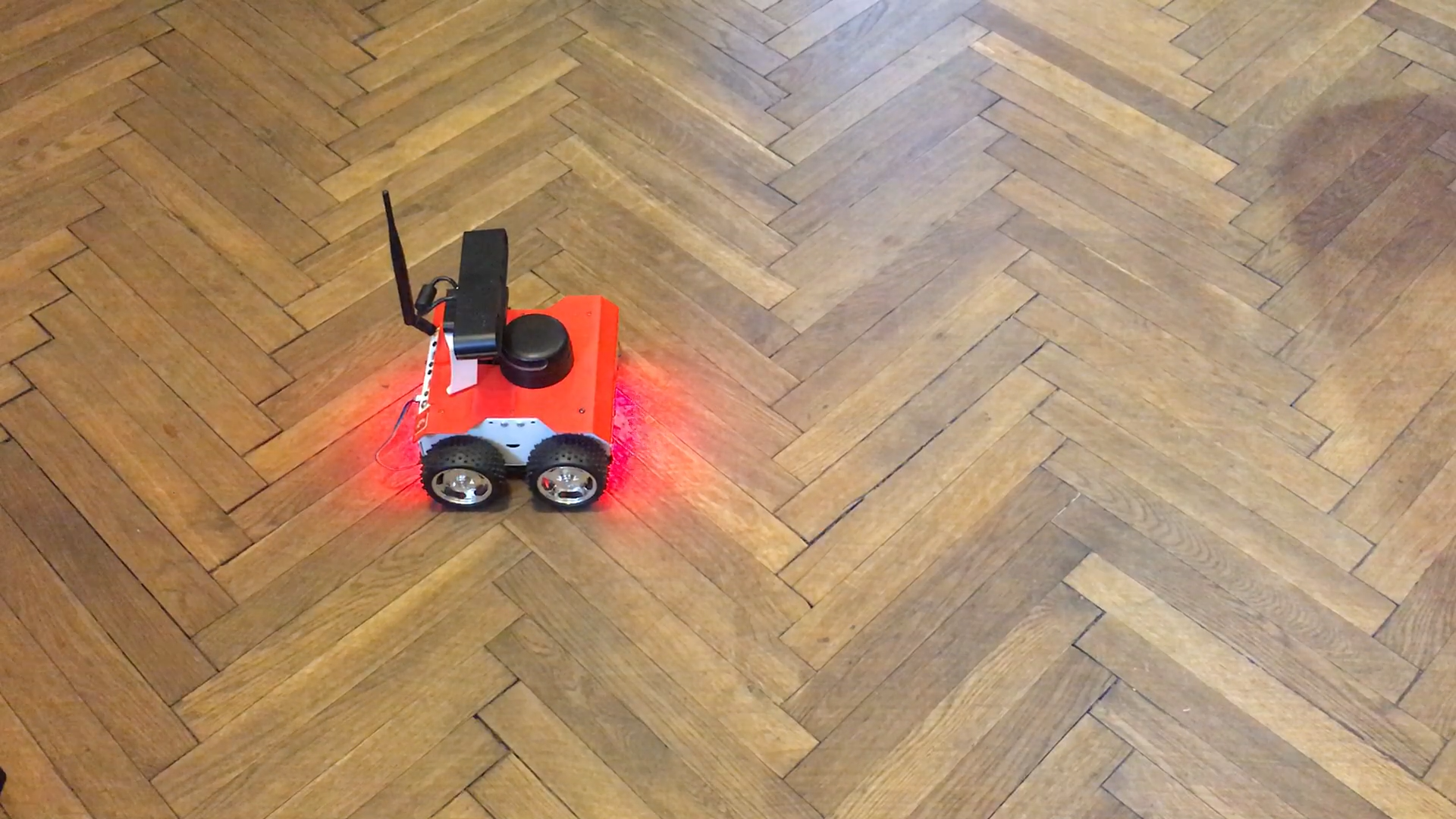
This node listens to messages on cmd_vel topic and changes leds color to green whenever the new, non zero speed target appears. When there is no new commands or target speed is zero then the illumination is red.
You can use a keyboard teleoperation node to check how it works:
rosrun teleop_twist_keyboard teleop_twist_keyboard.py
move_base example
In this example we will provide a distinct animation for each move_base/status ID in autonomous navigation. The visual differentiation between robot's states can be helpful in debugging ros autonomous applications and it also looks awesome. Check it out:
Here are the states that will be visualized:
| Behavior | GoalStatus ID | Command |
|---|---|---|
| LEDs off | PENDING | SANI S #000000 |
 | ACTIVE | SANI F #0038ff |
 | PREEMPTED | SANI F #fda600 |
 | SUCCEEDED | SANI F #32ae00 |
 | ABORTED | SANI B #c90000 |
To use the feature, first launch a rosbot_ekf all.launch:
roslaunch rosbot_ekf all.launch
PRO:
roslaunch rosbot_ekf all.launch rosbot_pro=true
After that run the example node:
rosrun rosbot_ekf move_base_ws2812b_example
Now you can use any ros application that uses move_base package like Route admin panel.
Route admin panel
The Route admin panel is a web user interface that allows you to navigate ROSbot autonomously between set of destination points. It is excellent application to test our leds.
To install it on you robot please follow this manual :Route admin panel installation.
After that you can launch it using:
roslaunch route_admin_panel roslaunch route_admin_panel demo_rosbot_mbed_fw.launch
PRO:
roslaunch route_admin_panel roslaunch route_admin_panel demo_rosbot_pro_mbed_fw.launch
There is no need of running roslaunch rosbot_ekf all.launch in this case, since it is already included.
After that run the example node:
rosrun rosbot move_base_ws2812b_example
Once all nodes are running, go to web browser and type in address bar:
ROSBOT_IP_ADDRESS:3000
Set destination points and run autonomous navigation. You should observe ROSbot changing its led's animation accordingly to the navigation state.
Summary
This tutorial should give you the idea about using ws2812b rgb leds with ROSbot and employing them in your ROS applications. You can use the presented examples as starting point of your own signalization system. The example nodes used in this tutorial are located in rosbot package. If you want to create custom animations, check out the new [rosbot firmware source code]((https://github.com/husarion/rosbot-firmware-new).
by Szymon Szantula, Husarion
Need help with this article or experiencing issues with software or hardware? 🤔
- Feel free to share your thoughts and questions on our Community Forum. 💬
- To contact service support, please use our dedicated Issue Form. 📝
- Alternatively, you can also contact our support team directly at: support@husarion.com. 📧