ROSbot 3 preview
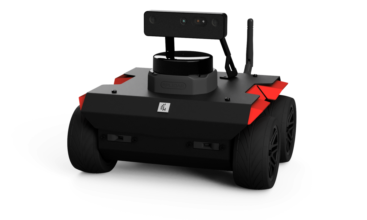
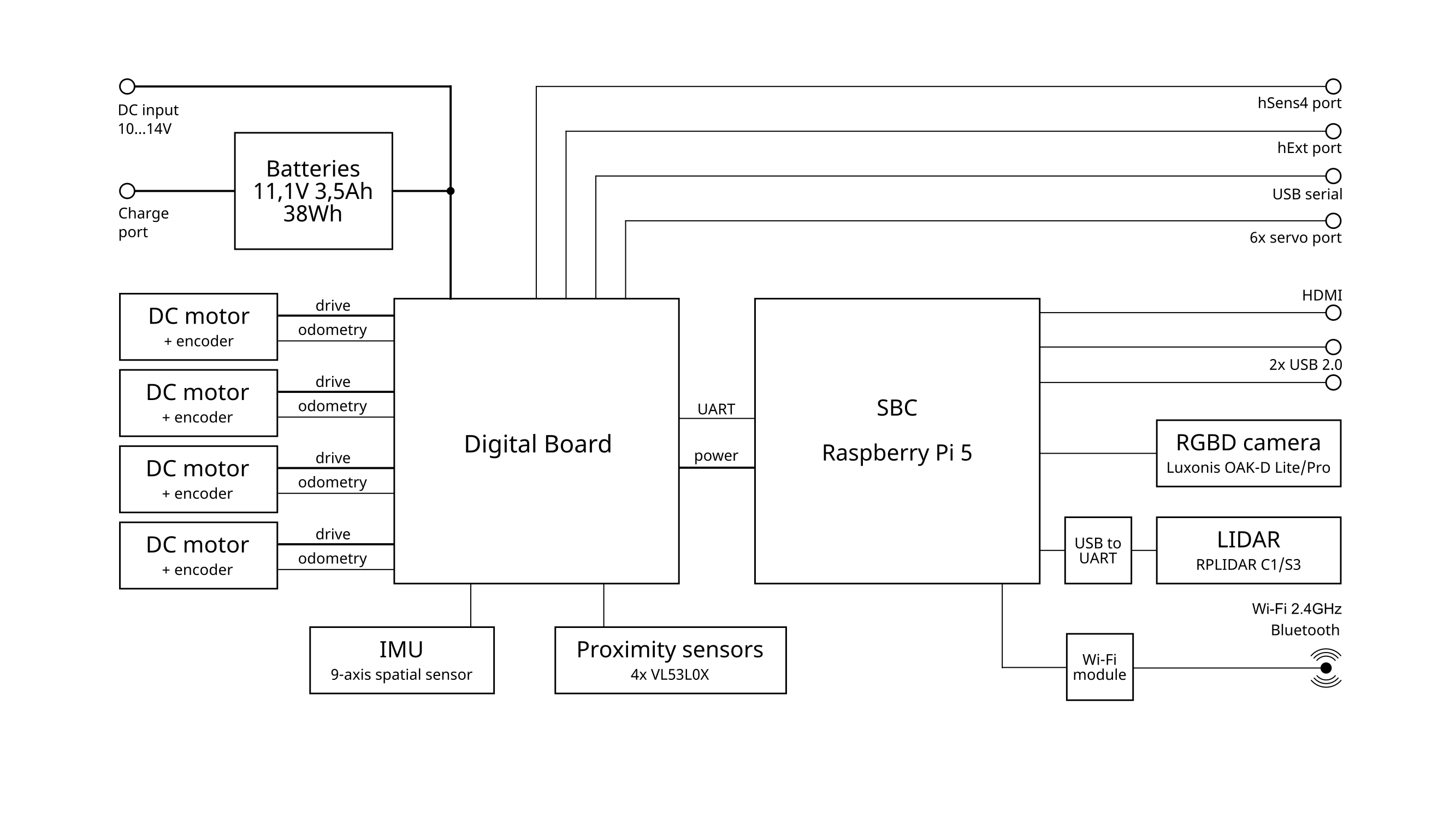
ROSbot 3 / ROSbot 3 PRO is an indoor mobile robot platform, purpose-built for research and education. Powered by a Raspberry Pi 5 and constructed with a durable 1.5mm alloy chassis, it offers robust performance and reliability. The ROSbot 3 features a SLAMTEC C1 LIDAR and Luxonis OAK-D Lite camera, while the ROSbot 3 PRO is equipped with an enhanced SLAMTEC S2 LIDAR and OAK-D Pro camera for superior perception and SLAM capabilities.
The open-source ROS 2 drivers are pre-installed and configured, enabling out-of-the-box operation without additional setup. Users can start interacting with the ROSbot through a web-based interface or a gamepad—no coding required—making it an ideal platform for beginners and experts alike. With four DC motors, each equipped with independent quadrature encoders, ROSbot 3 provides precise motion control for navigating complex indoor environments, accelerating your research and development in robotics.
Architecture
User Interfaces
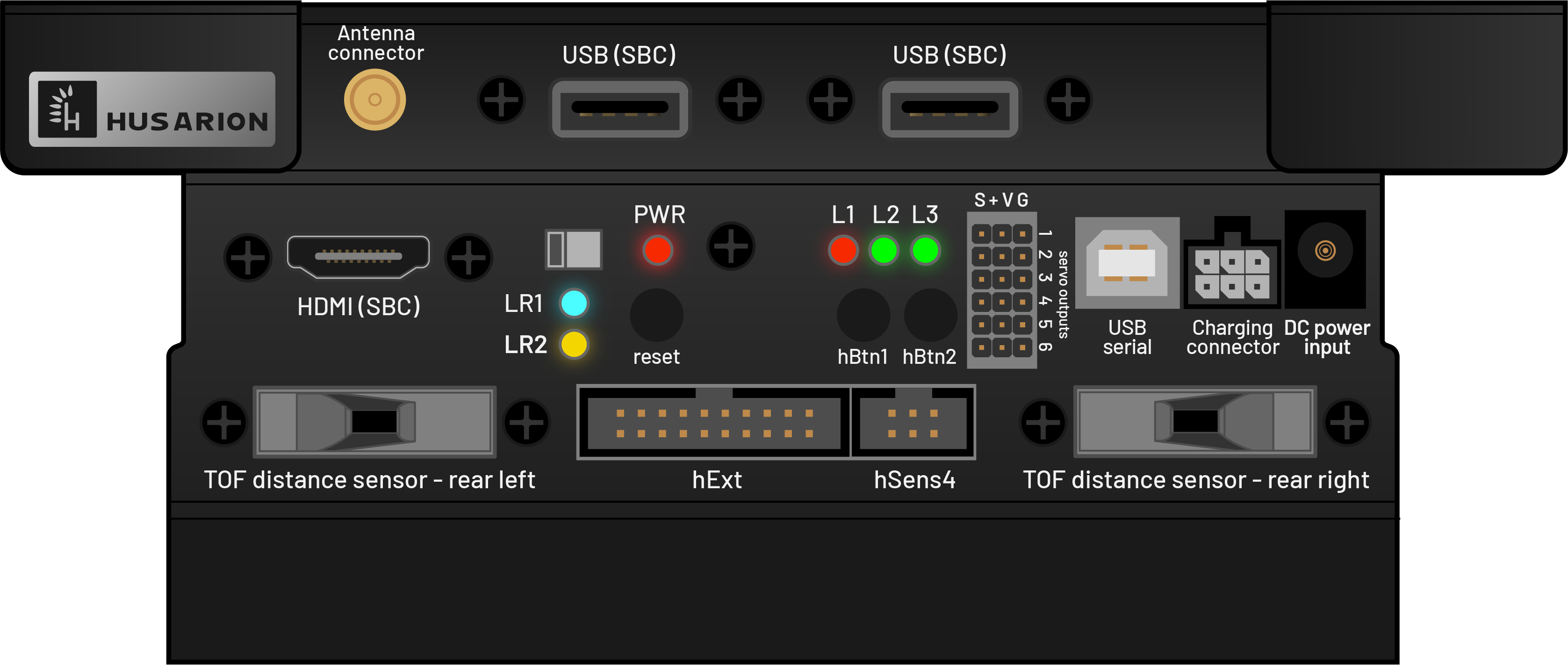
Available Interfaces on the Rear Panel of ROSbot
- 2 x USB-A Ports
- 1 x USB-B (Serial port for the STM32F4 microcontroller)
- 6 x Servo Ports (controllable via the ROS 2 API)
- 1 x hExt Port: 12 x GPIO / UART / SPI / I2C (accessible through modifications to the open-source firmware)
- 1 x hSensor Port: 4 x GPIO / UART / I2C (accessible through modifications to the open-source firmware)
- 1 x HDMI Port
- 3 x Signaling LEDs (L2 and L3 can be controlled via the ROS 2 API)
- 2 x User Buttons (hBtn1, hBtn2) (controllable via the ROS 2 API)
- 1 x Wi-Fi Antenna
- Power Switch
- Reset Button
- Charging Port (for universal charger)
- DC Input Power (connect a power adapter directly to supply the ROSbot from the mains; does not charge the battery)
Software Stack
ROSbot operates on Ubuntu 24.04 with ROS 2 Jazzy preinstalled. The ROS 2 drivers for the mobile platform, LIDAR, camera, and web user interface are available as snaps, which can be found in the Snapcraft Store.
Preinstalled snaps:
- rosbot
- husarion-webui
- husarion-depthai
- husarion-rplidar
ROSbot 3 is compatible with a wide range of tutorials and reference projects initially developed for ROSbot 2 / 2 PRO:
ROSbot 3’s software stack is fully open source, providing flexibility and transparency for your development needs:
Restoring ROSbot's System Image
If you need to restore ROSbot 3 to its default settings, download the ROSbot 3 Jazzy System Image (2024-09-30). Use Etcher to burn the image onto a microSD card, then insert it into the microSD card slot located on the side panel of ROSbot 3.
Quick Start Guide
Unboxing
Here's what you'll find inside the ROSbot package:
- ROSbot
- Carrying Case
- Wi-Fi 2.4GHz / 5GHz Antenna
- 3 x 18650 Li-Ion Rechargeable Batteries
- Universal Charger with Power Adapter
- Charging Cable
- MicroSD Card with pre-installed OS (already inserted in the robot)
- USB to Ethernet Adapter
Additional Items Needed for Initial Setup:
- Screwdriver
- HDMI Cable, Mouse, and Keyboard or just an Ethernet cable
Inserting Li-Ion Batteries and Mounting the Wi-Fi Antenna
Although your ROSbot arrives pre-assembled, you’ll need to install the power supply and attach the antenna to get it operational.
To Insert the Batteries:
- Turn ROSbot upside down.
- Unscrew the two screws located directly on top of the battery cover (ignore the other two screws nearby).
- Remove the battery cover.
- Insert the batteries as indicated by the symbols, ensuring the black strip is placed under the batteries for easy removal.
- Replace the battery cover and secure it with the screws.
For detailed instructions on charging the batteries, refer to this guide.
To Mount the Wi-Fi Antenna:
Simply screw the antenna into the SMA antenna connector located on the rear panel of ROSbot.
First run
To start your ROSbot, press the power switch located on the rear panel and connect the included USB-to-Ethernet adapter to the ROSbot’s rear panel. Then, connect the other end of the adapter with the Ethernet cable to your laptop.
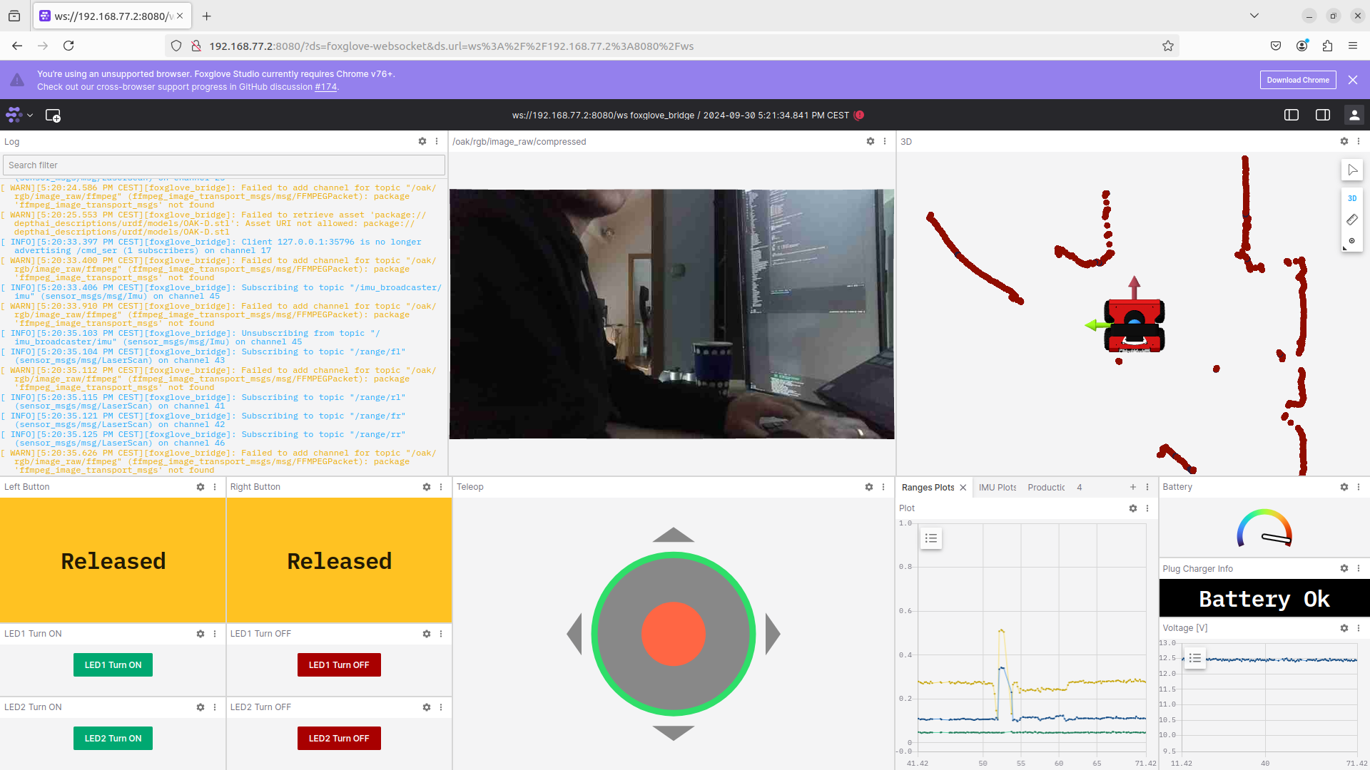
Accessing the Web UI
The web-based user interface is ready to use out-of-the-box. ROSbot runs a DHCP server for the Ethernet interface, so there's no need to configure a static IP address. Simply open the following URL in your web browser:
Connecting ROSbot to Your Wi-Fi Network
ROSbot uses the netplan tool to manage network configurations through a single .yaml file. To connect ROSbot to your Wi-Fi network:
- Connect to the ROSbot's shell via SSH:
ssh husarion@192.168.77.2 # password: husarion
- Edit the
/etc/netplan/01-network-manager-all.yamlfile and insert your Wi-Fi credentials in the"PLACE_YOUR_WIFI_SSID_HERE"and"PLACE_YOUR_WIFI_PASSWORD_HERE"fields as shown below:
network:
  version: 2
  renderer: NetworkManager

  ethernets:

    all-eths:
      match:
        name: eth*
      dhcp4: no
      dhcp6: no
      optional: true
      addresses:
        - 192.168.77.2/24

  wifis:
    wlan0:
      dhcp4: true
      dhcp6: true
      optional: true
      access-points:
        "PLACE_YOUR_WIFI_SSID_HERE":
          password: "PLACE_YOUR_WIFI_PASSWORD_HERE"
- Save your changes and apply the new settings using:
sudo netplan apply
- Check if your robot is connected to the Wi-Fi network by running:
iwgetid
- Find the ROSbot’s Wi-Fi IP address with the command:
ip addr show
You can now access the web user interface using the ROSbot’s Wi-Fi IP address.
Using a Logitech F710 Gamepad
You can also control ROSbot without coding by using a Logitech F710 gamepad (not included in the standard set).
To get started:
- Connect the USB dongle to a USB-A port on the ROSbot’s rear panel.
- Set the mode switch on the gamepad to X.
- Hold down the LB button (dead man switch) and use the control sticks to drive the robot.
With these simple steps, you can interact with ROSbot immediately, whether through the web interface or a gamepad!